
Building the Arbour Injection Machine V1.1
Injection Barrel Assembly
Required Tools
To complete this build you will need the following tools:
3mm Allen Key
2.5mm Allen Key
Small Philips Head Screwdriver (For Electronics)
Large Philips Head Screwdriver (PH2)
For the XL version, some steps are slightly different. These steps have a second step, just for the XL version. These are an addition to the original step, make sure to read both steps.
Building the Injection Barrel

Step 1
Take the black powder-coated injection barrel and place it on a flat surface.

Step 1 XL
Do the same for the XL version.

Step 2
Take the black powder-coated spacer (Some models are Stainless Steel instead) and Top Mounting Plate the Top.
Note: Some of our newer models have a much longer top mounting plate. Use this instead and orientate it to the left.

Step 2-B
Some of our newer models have a nut welded to the barrel for the thermocouple. The spacer and Top Mounting Plate can be slid over the nut. The top mounting plate has notch where the nut can fit through.

Step 2 XL
Do the same for the XL version.

Step 3
Bolt these together using 2x M5 16mm Bolt. Bolt these together tightly.

Step 3 XL
Do the same for the XL version.

Step 4
Next slide the larger Top Mounting Plate and the Hexagonal Barrel Spacer to the top of the barrel as shown.

Step 4 XL
Do the same for the XL version.

Step 5
Remove the Allen bolt from the 3x heat bands and slide the heat bands up the barrel. You may need to open the heat bands a little more to allow them to slide on the barrel. Note that the first one is a slightly different orientation than 2 & 3.
The first heat band should be 8cm away from the bolted metal plate, the lowest heat band should be 1cm away from the end of the barrel.
While doing this place the pipe clamp between 2 & 3.
IMPORTANT: The cables for the heat bands and the screw point of the pipe clamp should be pointing towards the camera, and away from the table
Tighten the heat bands in place by reinserting and tightening the Bolts.

Step 6
Next, remove the 2x screws from the Thermocouple connector to remove the cover. The loosen the remaining 2 screws to slide the tips of the green and red wires under.
Make sure that Green is located at the K point and Red is located at +.

Step 7
Then slide the heat shrink up the cable and heat with a lighter or heat gun. Making sure not to melt the plastic of the connector.

Step 8
Then ensuring no cables are trapped, place the cover back onto the connector, making sure not to over tighten the screws.

Step 9
Next, screw in the opposite end of the thermocouple into place on the Pipe Clamps. These need to be adequately tight to ensure there is no movement in the future. However, please be cautious while tightening the thermocouple and avoid overtightening it.
Some newer models and the XL version have a nut welded to the barrel. Screw the thermocouple into place in the nut.
Step 10
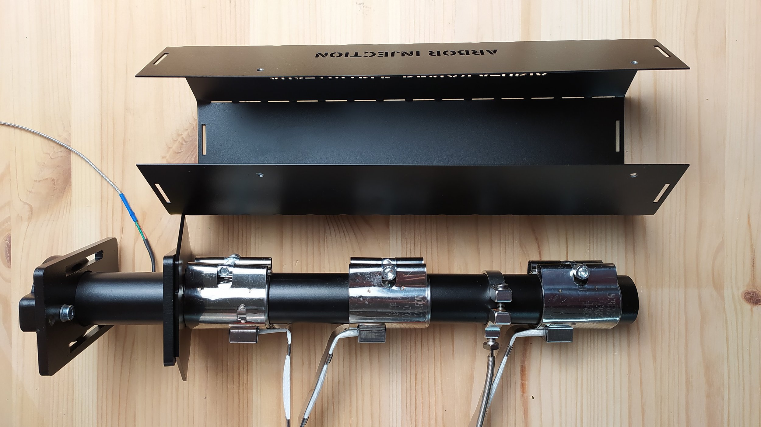
Your barrel should look something like this.

Step 11
Wrap the Rockwool around the barrel and slide the barrel into the housing as show. Making sure that the barrel remains covered on 3 of the 4 sides.
Note: When dealing with rock wool its important to use gloves to prevent irritation.

Step 12
Next add the final hexagon piece to the end, sliding the 3/4” to 1/2 “ reducer through the center hole and tightening onto the end of the barrel.
The hexagonal top and bottom spacers have 3 tabs on each. 2 short and 1 long. The Longest one should be located furthest away from the opening. Or in this case on the side resting on the table.
Make sure the heat band cables have a layer of insulation behind them. Everything should now be pointing up towards you and away from the barrel.

Step 13
Using the 2x 70cm and 1x 80cm 3 core cables connect the Blue Connectors, by separating them into 4 parts. Sliding the first 2 parts on before the next step.

Step 14
Slot the cables into the plug points. Brown to the left, Green in the center, and Blue to the right. Ensure these are tightly fitted. By pulling on the cable and ensuring nothing comes loose.

Step 15
Then reassemble the plug.

Step 16
Take the opposite end of the 3 cables with the blue plugs and connect the Brown and Blue cables to the ceramic connections of the heat bands. The 70cm should be connected to the top 2 heat bands, and the 80cm should be connected to the heat band closest to the nozzle.
Remove the screw from each of the heat bands and place the Green cable with the red loop connection under the screw as shown.

Step 17
To ensure no cables later come loose by mistake wrap the connectors with Electrical tape, working slightly up the wire ensuring no ceramic or uninsulated wires can be seen.

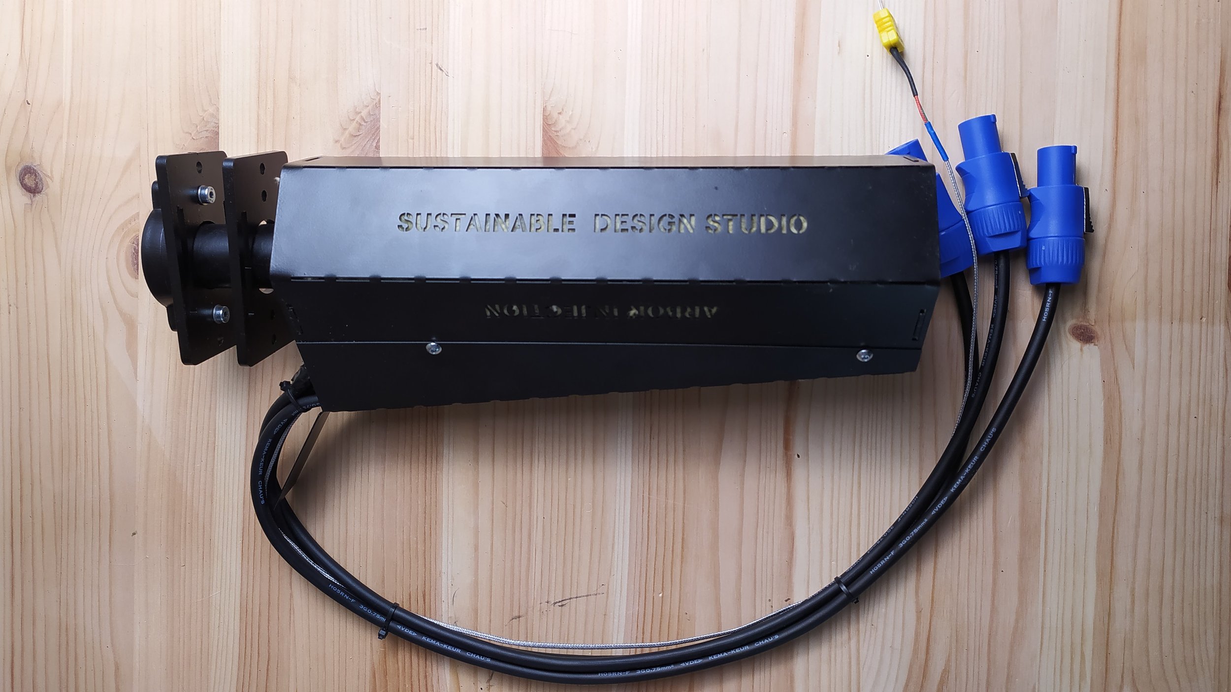
Step 18
Your barrel should now look something like this.

Step 19
Next, add the rear cover using the 4x M4 8mm Bolts. Ensuring no cables are pinched in the process. Take your time with this process ensuring you don’t trap any cables.

Step 20
Finally, use cable ties to neaten up the cables. cutting them short where possible to keep the whole thing neat and tidy.
Step 21
You are now done with the barrel. Time to move onto building the rest of the machine!

Step 21 XL
You are now done with the XL barrel. Time to move onto building the rest of the machine!