
Building the Arbour Injection Machine V1
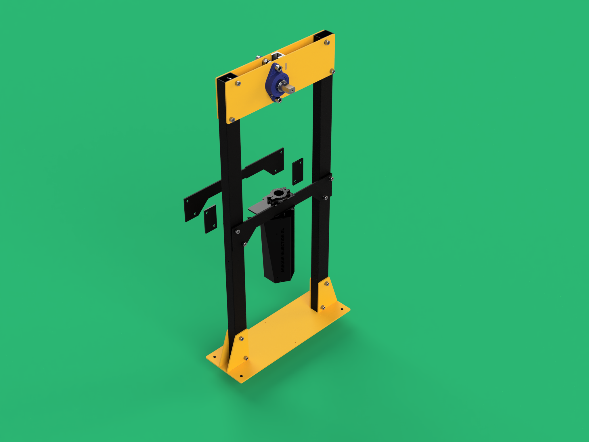
Arbour Injection Full Assembly
Required Tools
To complete this build you will need the following tools:
Adjustable Spanner/Wrench
Metric Allen Keys
Needles Nosed Pliers
For the XL version, some steps are slightly different. These steps have a second step, just for the XL version. These are an addition to the original step, make sure to read both steps.

Step 1
First, start by taking the large base piece, placing the base on a rug or matt to prevent the machine from scratching your floor or the floor damaging the paint as you build.

Step 2
Next, connect the 2 vertical tubes to the base using 4x M10 65mm bolts as shown. Make sure to put washers on either side of the bolt, and securing in place with the M10 Lock Nuts. At this point, there is no need to tighten the bolts and is best to leave everything slightly loose for the following steps
Note: The hole alignment is different at the bottom of the tubes vs the top. So if the holes don’t line up, rotate the tube.
IMPORTANT: There is a tube with 2 small holes mid way up the tube. Make sure this goes on the left side, with the holes facing out to the left. This is for mounting the Electronics box.

Step 3
Taking each of the large bearing plates, attach the 30mm bearings as shown. Use the 2x M14 bolts to secure the bearing in place. As always place a washer in the bolt and just before the M14 Locknut is added.
For now its best to leave these bolts loose.
Repeat this step for the second large bearing plate but take extra care to ensure the bearings mirror each other.

Step 4
Take the 30mm Diameter shaft and place the small keyway into the slot.

Step 5
Then slide the Spur Gear onto the shaft ensuring that it is evenly placed exactly on the keyway.

Step 6
Then add a rubber washer to each side of the gear, and a small and large spacer (4mm & 10mm Spacer) as shown.

Step 7
Then slide the shaft into the previously secured bearing assembly as shown.

Step 8
Using the M5 x 10mm bolts, connect the 1x Stainless Steel Spacers and 1x 1mm Shims to each of the yellow plates. The 1mm shim is placed against the Yellow Plate before placing the thicker spacer.
Then slot the Stainless Steel Backing Plate to the Yellow Plate. It should be orientated so that it matches this photo and lines up at the top.
Note: Inserting the SS Backing Plate may strip the paint (but this ok as it needs to be tight!)
Note: pay extra special attention to the Stainless Steel Spacer Orientation. This should be flush from the top and about 2cm off the bottom.

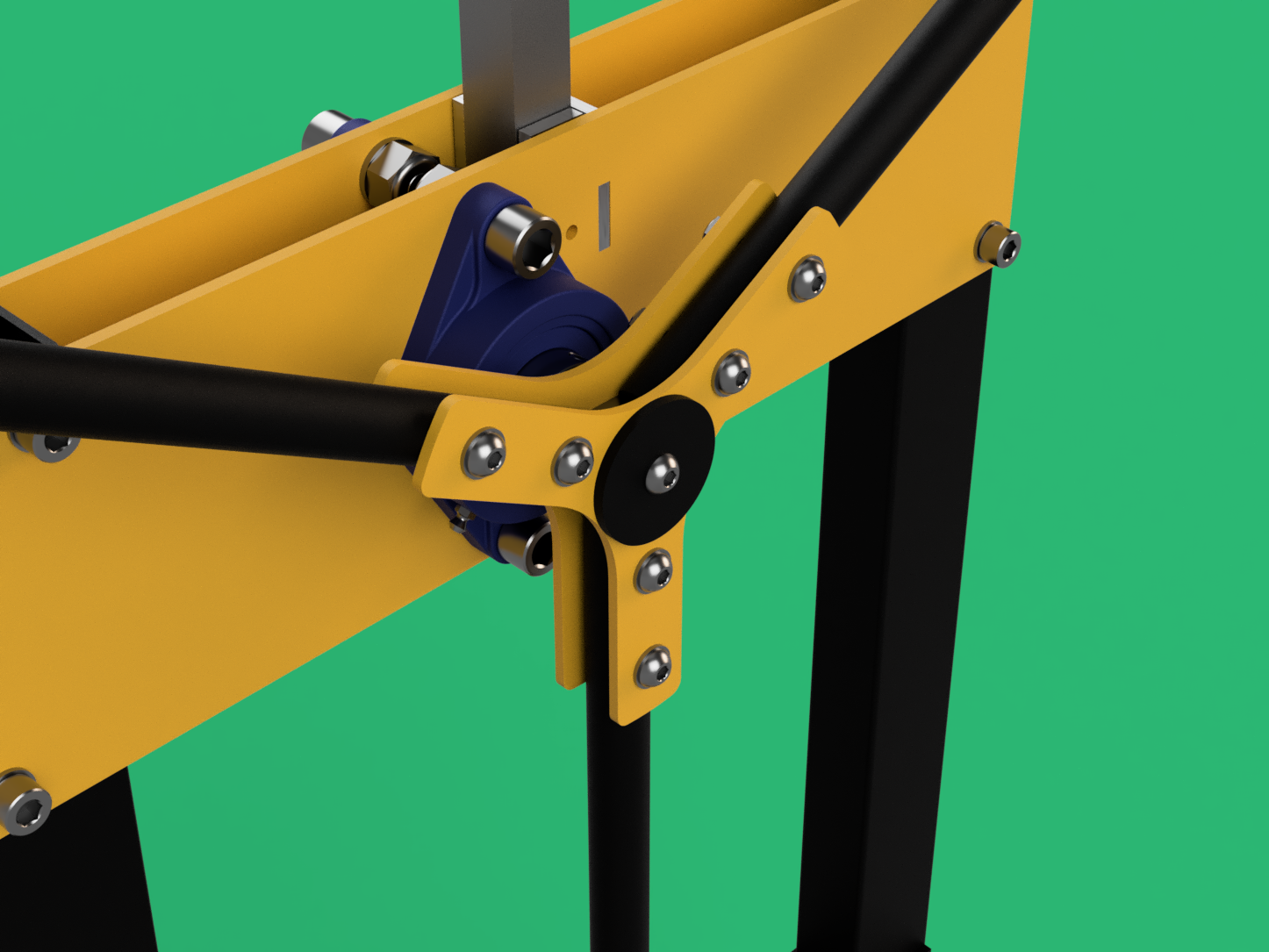
Step 9
Then taking the other Yellow Plate, align the shafts, and Backing Plate and slide the two plates together. Gentle tapping with a rubber mallet may be required to join the 2 pieces.
In some cases, the Rubber Washer, and 4mm Spacer may push the bearings too far apart. Feel free to remove either the rubber washers or 4mm spacers from either side evenly until the bearings fit.

Step 10
If you have trouble pulling the 2 plates together check that the small grub screws on the bearings have been loosened. Then use the 1x M10 65mm bolt as shown. Make sure to put washers on either side of the bolt, and securing in place with the M10 Lock Nut. This should help pull the two plates together. Once together, loosen in preparation for the next step.

Step 11
Next, connect the 2 vertical tubes to the recently assembled top plates using 4x M10 65mm bolts as shown. Make sure to put washers on either side of the bolt, and securing in place with the M10 Lock Nuts. At this point, there is no need to tighten the bolts, and is best to leave everything slightly loose for the following steps

Step 12
Then take the heat-resistant center plates, there are 2 that look identical however, 1 has a few more holes (for wires). Use the one with fewer holes, and use 4x M10 65mm bolt as shown. Make sure to put washers, but this time don’t put the extra bolts and washers on the opposite side just yet.

Step 12 XL
For the XL version, add the spacer plates in between the heat-resistant center plates and the vertical tubes. Use 4x M10 70mm bolts and washers.

Step 13
Then take the barrel unit and align the notches of the horizontal bar with the top plate of the barrel.

Step 13 XL
Do the same for the XL version. Make sure that the cables go left.

Step 14
Then with the second heat-treated plate (The one with the extra holes) Align the holes to the left of the machine and bolt it in place using the 4 washers and 4 locking nuts.
Note: Make sure the cables also go to the left.
Step 14 XL
For the XL version, again add the spacer plates in between the heat-resistant center plates and the vertical tubes.

Step 15
While the barrel is not fully fixed. Slide the Arbour Rack with the teeth aligned with the spur gear and place the barrel underneath the rack when in place.
Note: Take extra care here not to drop the rack.

Step 16
With the 2x M5 55mm bolts, slot them through the holes on the top plate and align them with the holes in the bottom plate. Using a M5 Lock Nut, tighten this, locking the barrel securely in place.
Note: This space is tight, you will need to use the needle-nosed pliers to do this.

Step 16 XL
This step is the same for the XL version.

Step 17
Now is the time to build the handle.

Step 18
Start by first taking one of the 2 Yellow Handle laser cuts and lay the 3 solid metal handles in place. Aligning the holes as shown.

Step 19
Then placing the remaining Yellow Handle laser cut, start placing the M8 40mm button boltw. With a washer on either side of the laser cuts and secured in place using the M8 locking nut in the 6 holes. Make sure when you do this that the laser cuts line up as seen in the image, and that for now the nuts are in place, but are loose for the following steps.

Step 20
Now slide the handle assembly onto the shaft. This maybe very tight (due to the powder coating). If the handle needs a bit of encouragement you can use a rubber mallet, but avoid using a metal hammer otherwise you may risk damaging the paint.
Step 21
Once the laser cuts are aligned on the shaft (they don’t need to be fully pressed in), use the M8 20mm bolt and large painted laser cut washer to press the hand crank into place. Then once secure, tighten all the bolts and nuts on the handle to ensure non of the handles can wobble or come loose.

Step 22
Now we add the plunger. By using the hand crank we need to lift the rack to its highest position. Then place the plunger underneath and place the M10 45mm Hex Bolt locking the plunger in place. Add a M10 lock nut to the opposite side (back) and tighten until the plunger is secure, but is free to pivot on the end.
Note: Now is a good time to check the plunger and handle mechanism move smoothly. We may need to adjust the rack and pinion system if it feels loose or stiff. You can do this by adjusting the bearings in their slots to apply more pressure against the rack.
You may also find that the plunger is quite tight in the barrel or is not aligned properly. Gently press on either the right or left side of the machine until the barrel and plunger are aligned and moving smoothly. Once smooth tighten up the 12 M10 bolts on the verticals. Locking the frame in place.

Step 22 XL
The XL version has a brass plunger. Fasten the brass plunger firmly onto the thread of the plunger shaft.

Step 23
Next we need to add the hopper. To do this adjust the plunger position so we can slide the hopper into place. Make sure the hopper shoot faces toward the back of the machine. Fix in place with 2x M5 6mm Button Head Bolts.
Note: The image is taken from the rear of the machine.

Step 24
On the left side of your machine, your should have 2x small holes on the outside of your vertical bar. (STEP 2) Using these holes place the Electronics Box Mount Plate into place using the 2x M5 8mm and 2x M5 washers. Make sure this is nice and tight to avoid slipping.

Step 24 XL
The XL version has a K-mounting plate. Make sure the K is pointing towards the back of the machine, as shown.

Step 25
Now taking the electronics box, add the 4x M5 standoffs. Make sure these are fairly tight.

Step 26
Now using the 4x M5 8mm bolts. Secure the electronics box to the frame as shown.

Step 26 XL
This step is the same for the XL version.

Step 27
Finally, plug the 3 quick connection plugs into their respective colour-coded sockets (Blue with Blue) on the electronics box. These should be pressed in and twisted to lock into place. Then connect the thermocouple connector for the barrel to the electronics box. Your model may look slightly different from the image used.

Step 28
Next on the base plate secure the jack mount using 2x M5 8mm button bolts.

Step 29
Then taking the jack, and mould plate, press the mould plate onto the jack (Might be a tight fit) and place the jack in place under the nozzle.
It’s important to note if the machine is not intended to be mobile that it is securely bolted down to the floor or screwed onto a wooden base with a larger footprint.