
Retrofit your Injection Mini
A step-by-step guide to removing the springs from your Injection Mini. Making this change will increase the function of your machine’s plunge system and its longevity.
To complete this build you will need:
3mm Allen Key
2x 8mm Spanners (or adjustable spanners)
Measuring Tape / Ruler
Step 1
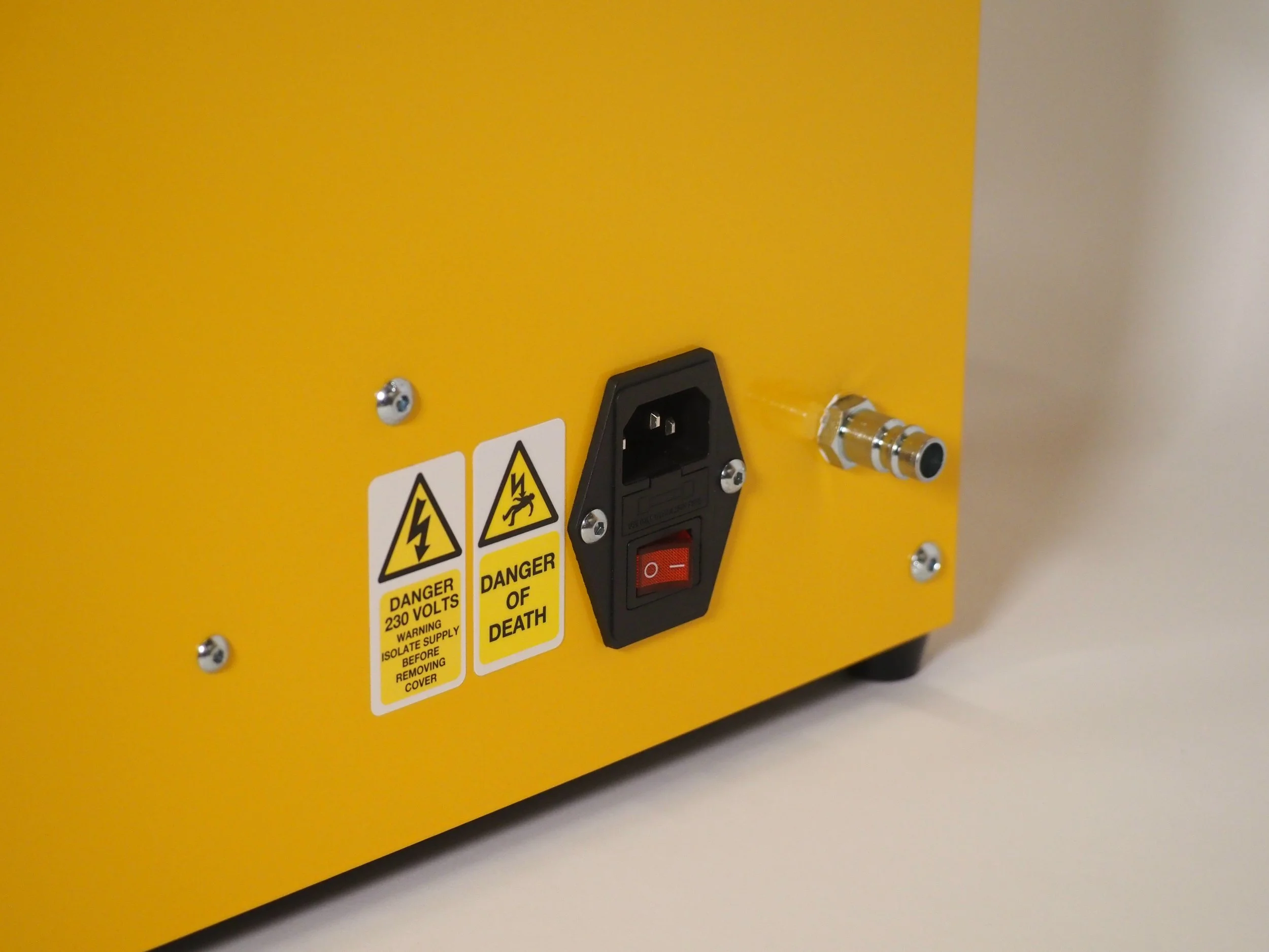
To ensure a safe build, disconnect your air compressor and plug. Then wait for your machine to completely cold before beginning work.
Step 2
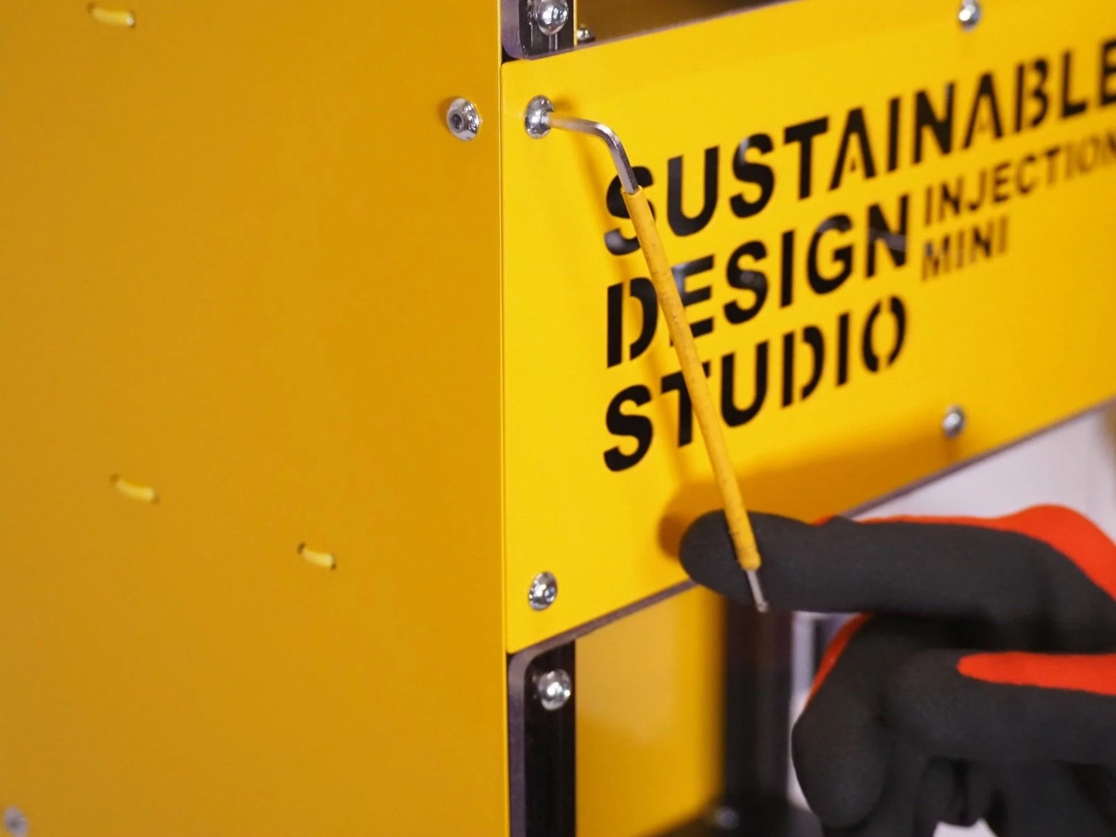
Using a 3mm Allen Key, complete one half rotation counterclockwise on each bolt that fixes the yellow front barrel panel. Loosening these bolts will align the drop in tee nuts so that the panel can be removed.
Be sure not to rotate the bolts too much as this could cause the tee nut to fall into the extrusion. If this happens use your Allen Key or a magnet to retrieve the nut.
Step 3
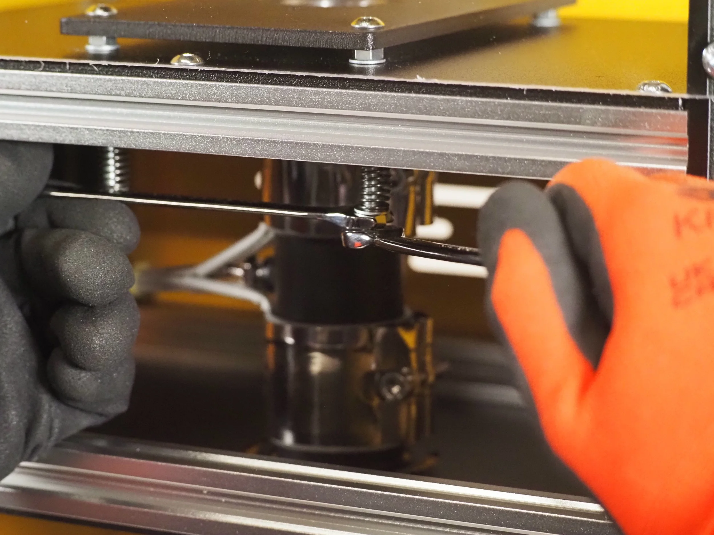
With the front panel removed you will be able to locate the four; bolts, springs and fixings that are attached to the barrel.
With your spanners remove the nuts and springs from each bolt so that they are left bare. Leaving the bolt in place.
Step 4
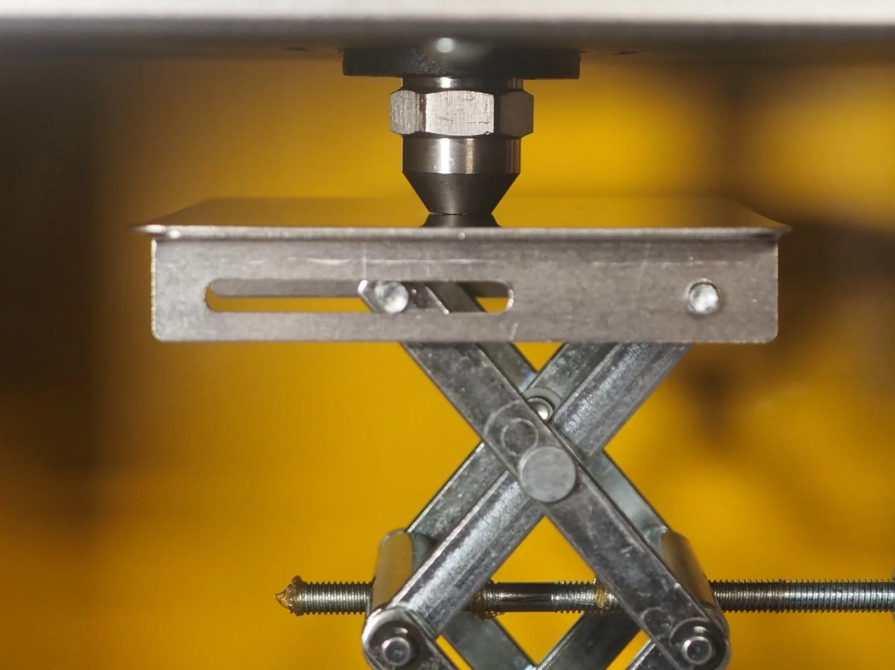
Place 6 of your plywood spacers in a stack on your machine’s mould area panel with the scissor jack on top. Expand your jack until it reaches the barrel’s silver nozzle.
Continue raising the jack until the tip of the black barrel sits 5mm under the edge of the horizontal black plate. Use a measuring tool to ensure this distance is correct.
Step 5
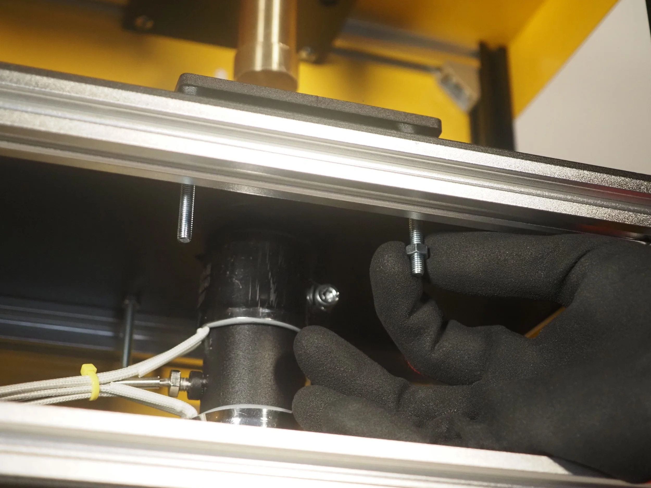
With the barrel height now set, place 1 nut on each of the barrel’s 4 bare bolts that previously held the springs. Position each nut so that they touch the top black horizontal plate. These nuts only need to be placed against the plate, acting as a marker, and should not adjust the height of the barrel.
Step 6
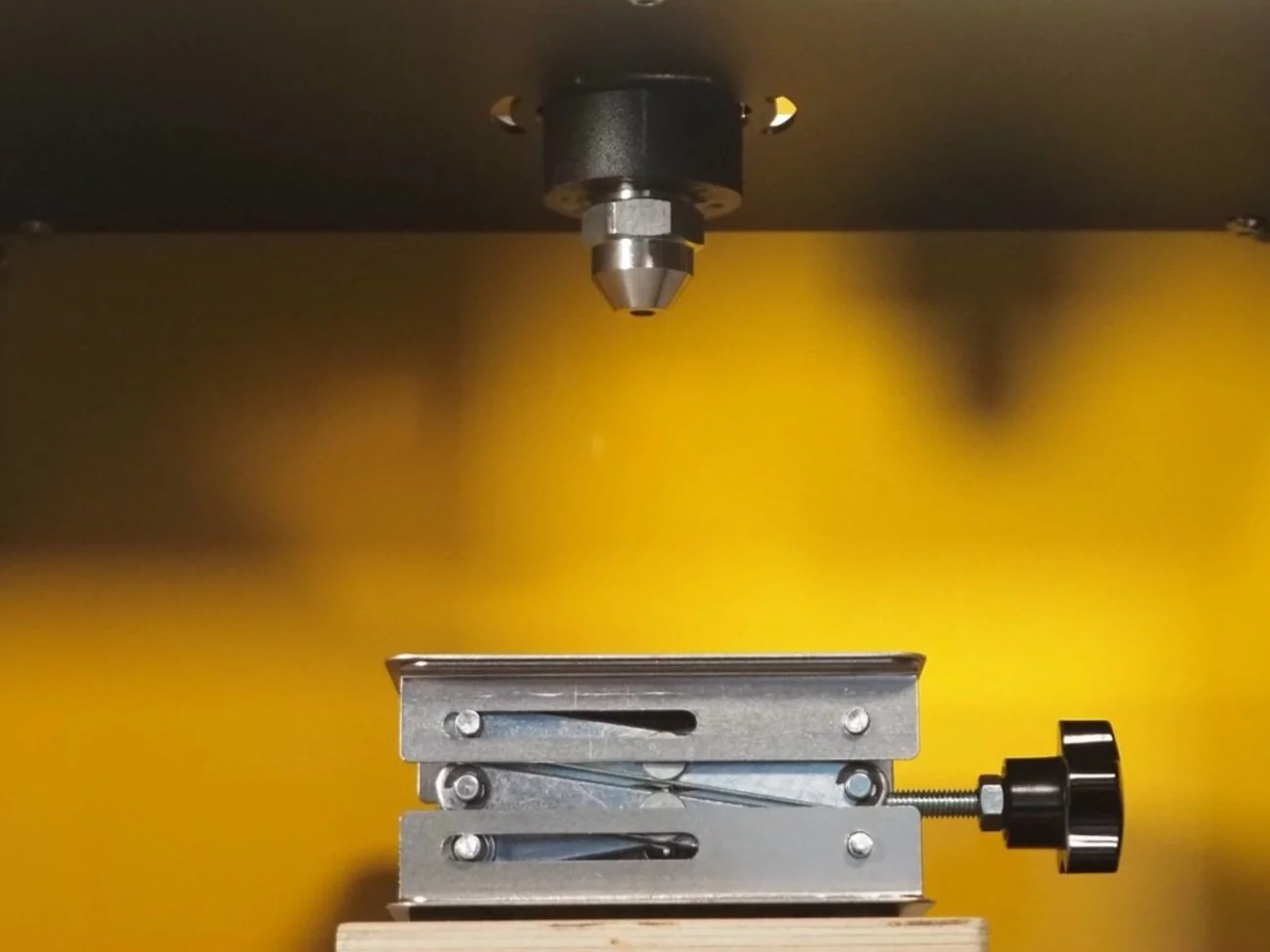
Lower your jack and allow the barrel to side down into its resting position.
Step 7
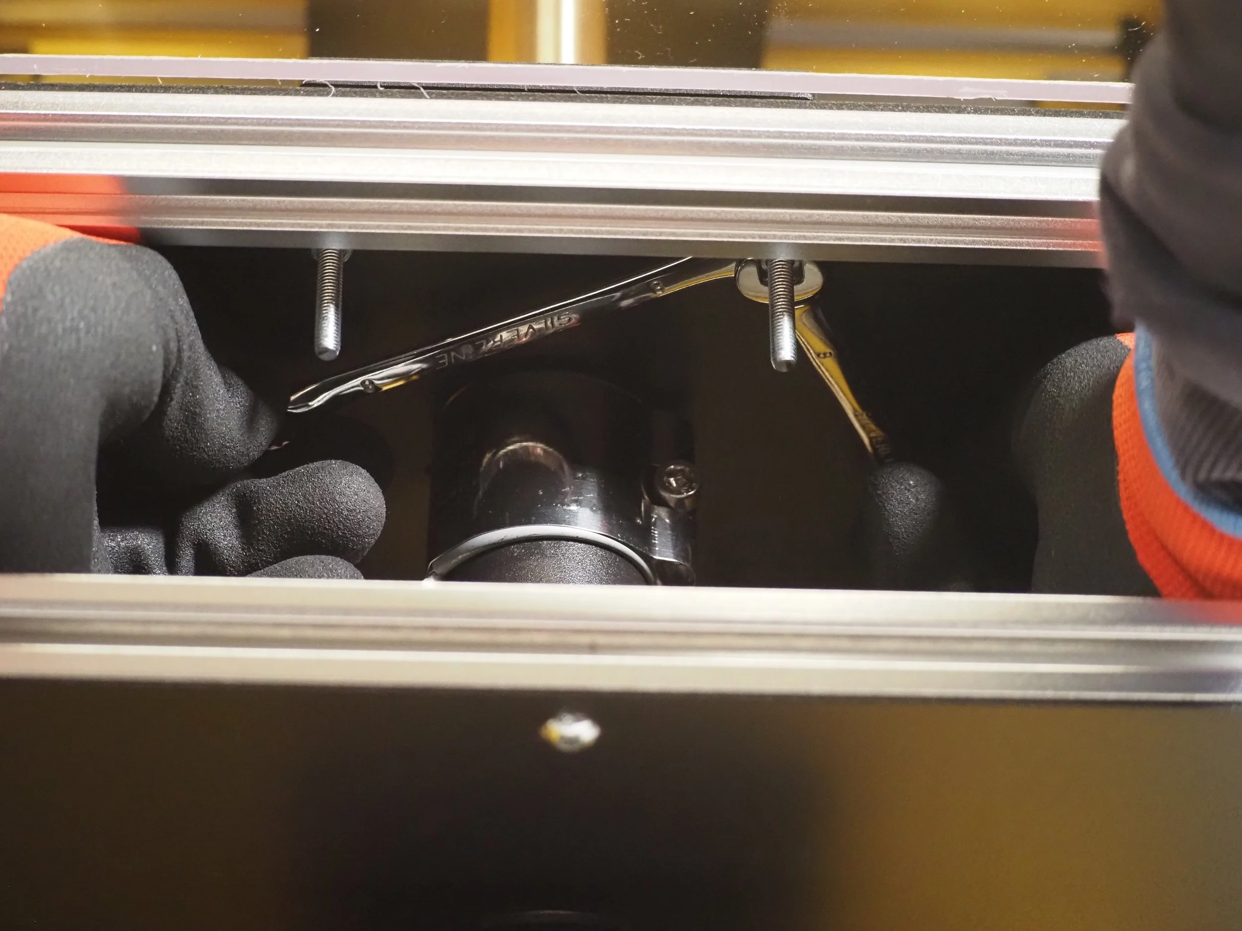
Without adjusting the positioning of the first nut, add an additional M5 nut to each bolt until they touch.
Using your two spanners, lock the 8 nuts in place with a simple counterrotation.
With adequate pressure, these two bolts should now be firmly locked together. Please check this before moving onto the next stage.
Step 8
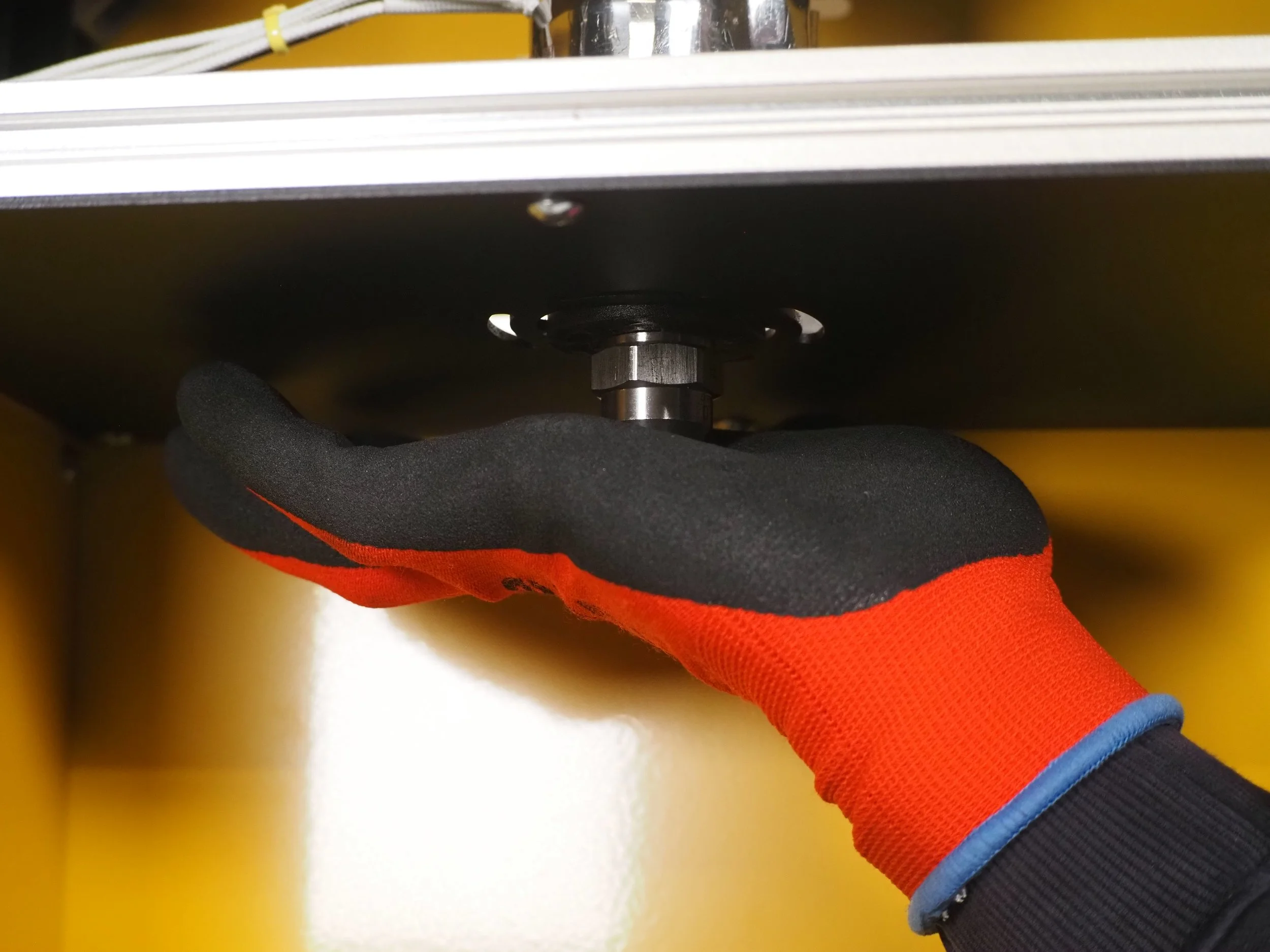
To check the travel of your barrel, press upwards on the silver nozzle. Measure again that the maximum travel leaves the desired 5mm gap. If this is not the case go back and to try readjusting the nuts, being sure their positioning does not change during tightening.
Check also that when your barrel slides to its resting position that it is still level above the top horizontal plate.
Step 9
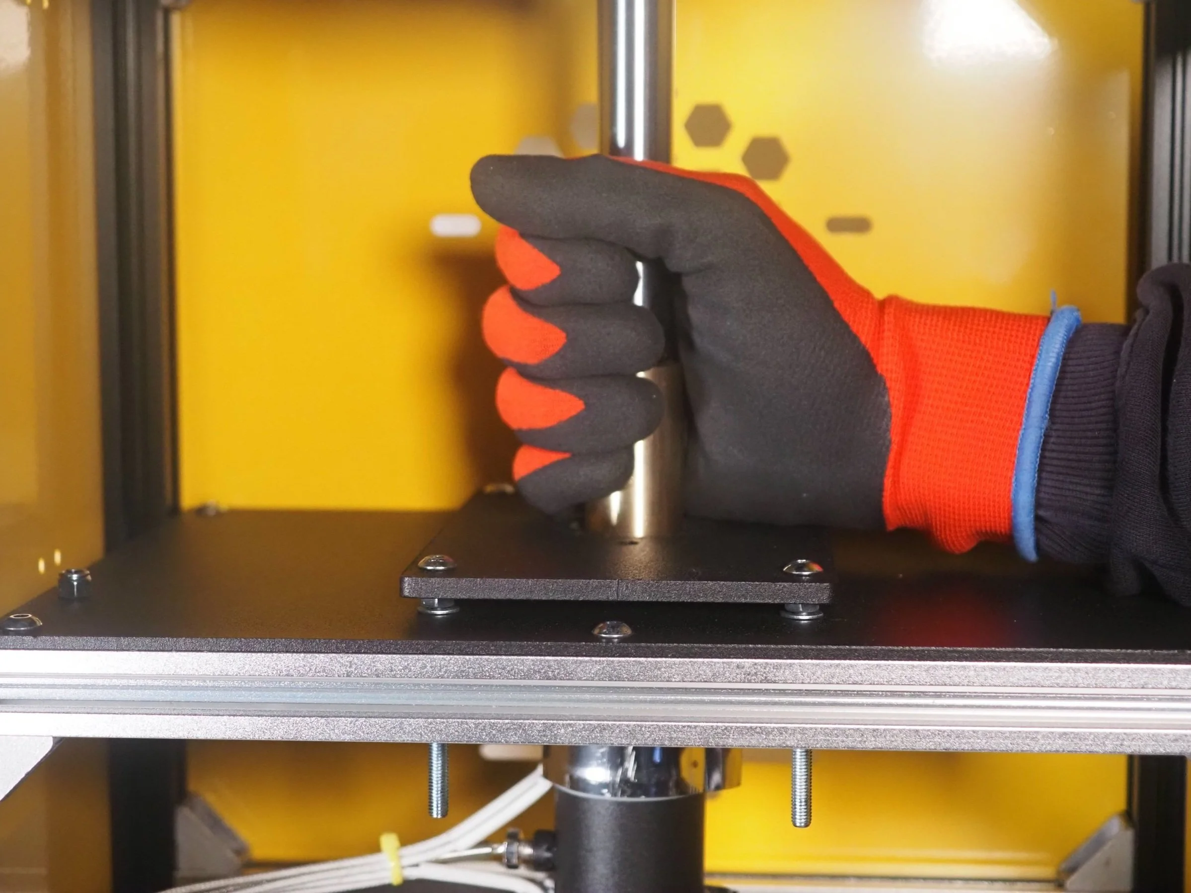
As a final check of your retrofitted barrel, confirm that the alignment of your plunger is precise. To do this, pull down on your piston until it enters the barrel. Make sure that it has the capacity to creates a smooth and full movement that does not catch on the ledge.
If you have an alignment issue, ensure that your barrel sits level, readjusting your new fixings where necessary.
Step 10
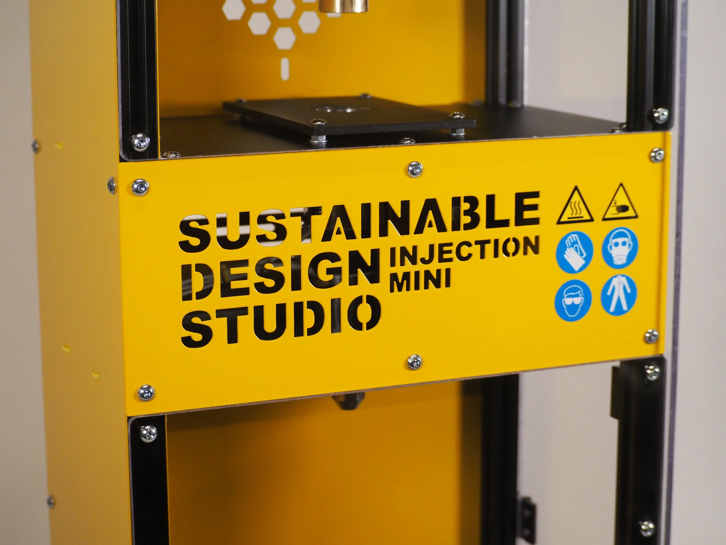
With your new barrel ready to go, reattach your Injection Mini’s front yellow barrel panel by using the 3mm Allen Key. Again slot the panel and its tee nut fixings into the extrusions and tighten until they lock the panel in place.
Congratulations! You have now taken your Injection Mini to the next level. With this change you should see a decrease in noise alongside a smoother mould removal process.
If you have any questions please don’t hesitate to get in touch.
contact@sustainabledesign.studio
Digital Product Passport
In the pursuit of transparency and our sustainability goals, we have created a digital product passport for the Injection Mini. This document contains information about where our parts are sourced alongside the environmental impacts of your purchase.