
Building your
Filament Maker V1.2
Tools to complete your build:
Allen Key Set (5mm, 3mm, 2.5mm, 2mm)
Spanner (13mm, 11mm, 7mm, 5.5mm)
PH0 Phillips Screwdriver
Safety Gloves
Pliers
Frequently Asked Questions
-
We recommend setting aside roughly 3 hours for this build. Those with more technical experience should be able to complete this in less time.

Lets get started making!
This build guide is suitable for the Filament Maker in all configurations. For ease of assembly, please make sure that you have your itemised parts list available to reference the part names mentioned in this build guide.

Step 1
You will Need:
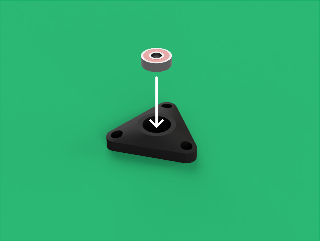
Strip Spool Mounting Plate (x1)
608ZZ Bearing (x1)
Take the Strip Spool Mounting Plate and press one 608ZZ Bearing into it as seen in the image.

Step 2
You will need:
M5 Lock Nut (x3)
Insert the three M5 Lock Nuts thread down, into the three hexagonal cutouts on Strip Spool Mounting Plate.
Step 3
You will need:
Strip Spool Bearing Mount (x1)
608ZZ Bearing (x1)
Take the Strip Spool Bearing Mount and press your second 608ZZ Bearing into it.

Step 4
You will need:
Main Body (x1)
Locate the correct holes on the Main Body, these are located on the top left-hand side.

Step 5
You will need:
M5x16mm Low Cylindrical Bolt (x3)
Align the Strip Spool Bearing Mount to these holes on the top side and insert the M5x16mm Low Cylindrical Bolts.

Step 6
Rotate the Main Body on to its side to match the orientation in this step.

Step 7
On the inside of the Main Body, align the Strip Spool Mounting Plate to the same holes and tighten the M5x16mm Low Cylindrical bolts into the part.

Step 8
You will need:
Strip Spool Mount (x1)
M8x45mm Hex Bolt (x1)
Insert the M8x45mm Hex Bolt into Strip Spool Mount ensuring that the hexagonal head is pushed fully into the Hexagonal cutout of the part.

Step 9
You will need:
M8 Washer (x1)
Slide one M8 Washer onto the M8x45mm Hex Bolt.

Step 10
Insert the Strip Spool Mount, Bolt and Washer through the Bearing of Strip Spool Bearing Holder and Strip Spool Mounting Plate.

Step 11
You will need:
M8 Washer (x1)
On the inside of the Main Body, slide another M8 Washer onto the M8x45mm Hex Bolt.

Step 12
You will need:
M8 Lock Nut (x1)
Screw on one M8 Lock Nut. This should be tightened down until there is no wobble in the Strip Spool Mount but it can still spin. Do not over tighten.

Step 13
You will need:
1.7mm Nozzle (x1)
CR10 Heat Block (x1)
Screw the 1.7mm Nozzle into the front of the CR10 Heat Block.

Step 14
Locate and remove the small bolt from underneath the Heat Block.

Step 15
You will need:
M3 K-Type Thermocouple (x1)
Insert the M3 K-Type Thermocouple into the threaded hole that you just removed the bolt from.

Step 16
On the Heat Block loosen the set screw.

Step 17
You will need:
40W Cartridge Heater 6x20mm (x1)
Insert the 40 W Cartridge Heater 6x20mm into the Heat Block, making sure that the cables from the heater go straight down. The same direction as the M3 K-Type Thermocouple.

Step 18
On the Heat Block, tighten the set screw back up. Making sure It's tight enough to where the 40W Cartridge Heater 6x20mm cannot be pulled out.

Step 19
You will need:
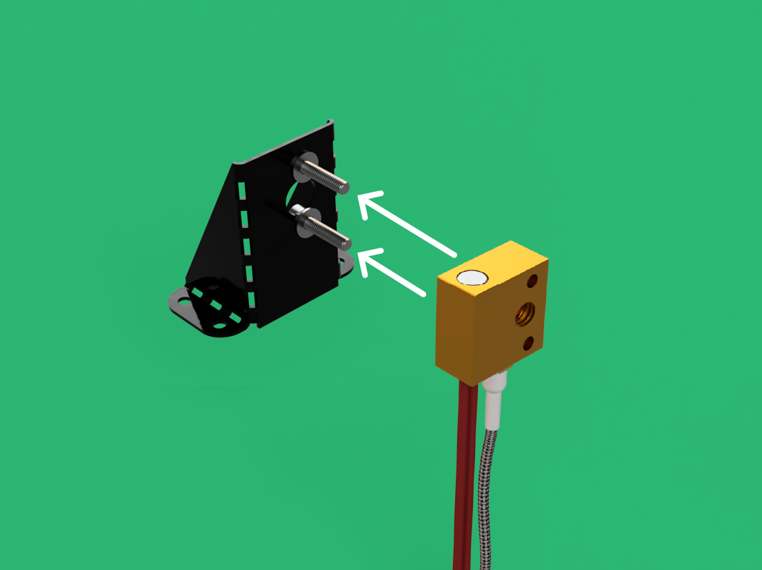
Extruder Mount (x1)
M3x14mm Cylindrical Bolts (x2)
Take the Extruder Mount and insert the two M3x14mm Cylindrical Bolts through the two smaller holes as see in the image.

Step 20
You will need:
M3 Washer (x2)
Rotate the assembly and place the two M3 Washers onto the two M3x14mm Cylindrical Bolts.
Step 21
Place the Heat Block onto the two M3x14mm Cylindrical Bolts.

Step 22
You will need:
M3 Hex Nut (x2)
Take the two M3 Hex Nuts and tighten the M3x14mm Cylindrical Bolts down the Heat Block.

Step 23
Locate the correct holes and cutout on the Main Body.

Step 24
From the top of the Main Body, feed the cables from the Heat Block into the cutout.

Step 25
Line up the Extruder Mount to these 4 holes.

Step 26
You will need:
M3x8mm Button Bolt (x4)
Insert four M3x8mm Button Bolts through the Extruder Mount and Main Body alignment.

Step 27
You will need:
M3 Lock Nut (x4)
On the inside, tighten four M3 Lock Nuts onto the M3x8mm Button Bolts.

Step 28
You will need:
Extruder Cover (x1)
Place the Extruder Cover over the Heat Block.

Step 29
Line up the Extruder Cover to the two holes shown in the image.

Step 30
You will need:
M3x8mm Button Bolt (x2)
Insert two M3x8mm Button Bolts through the Extruder Cover and Main Body.

Step 31
You will need:
M3 Lock Nut (x2)
On the underside, tighten on two M3 Lock Nuts onto the remaining bolts.

Step 32
You will need:
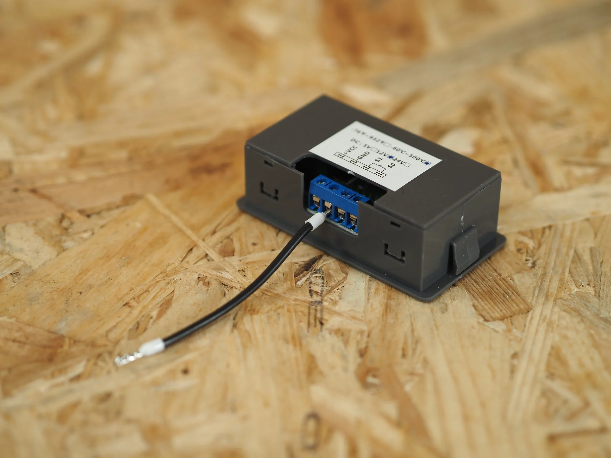
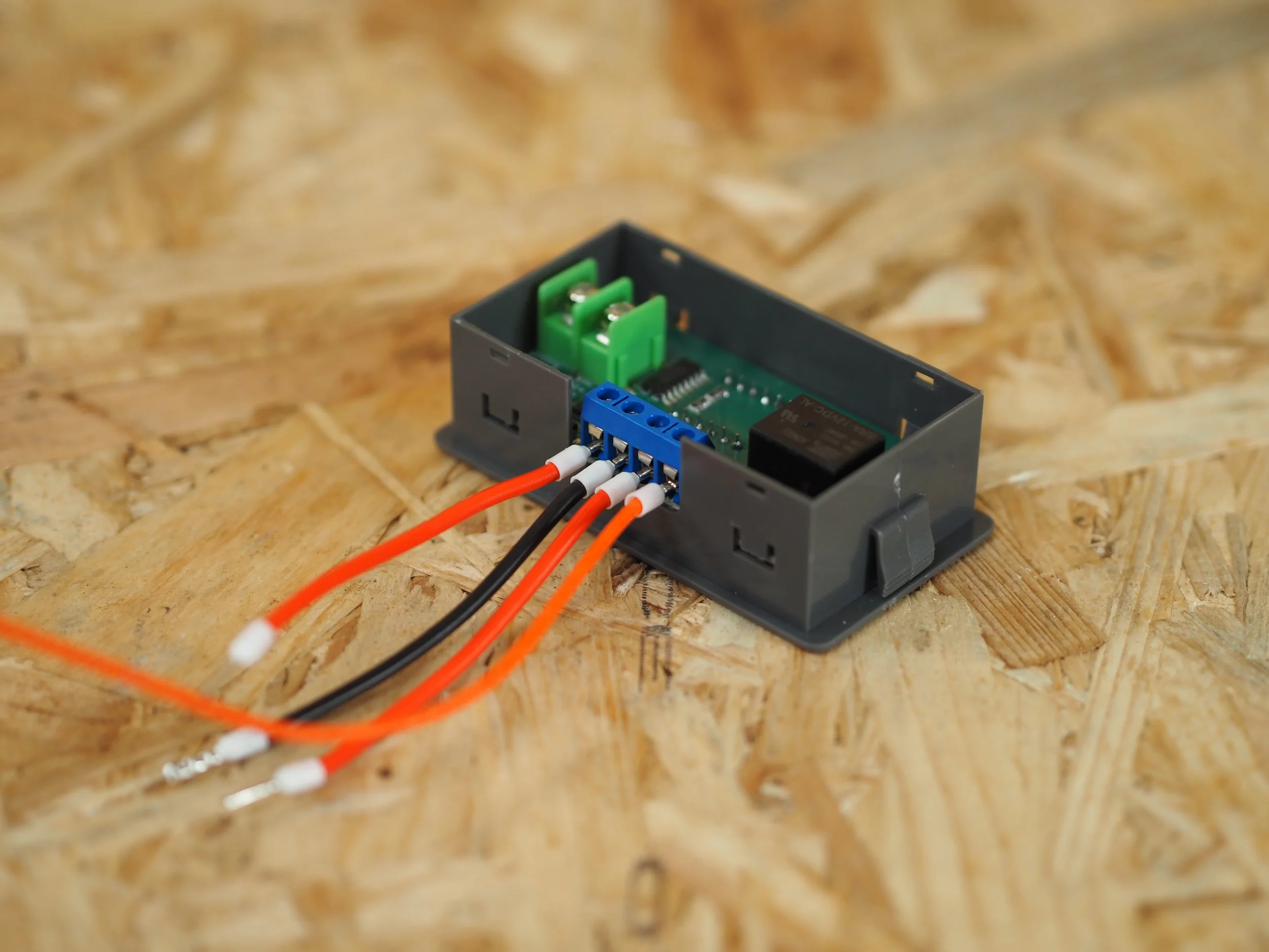
K-Type PID Controller (x1)
On the back K-type PID Controller, locate and loosen the four terminal block screws.
Step 33
You will need:
9mm Bootlace - Bootlace Black Cable (x1)
Insert the 9cm Bootlace - Bootlace Black Cable into the terminal marked GND and tighten down the screw.
Step 34
You will need:
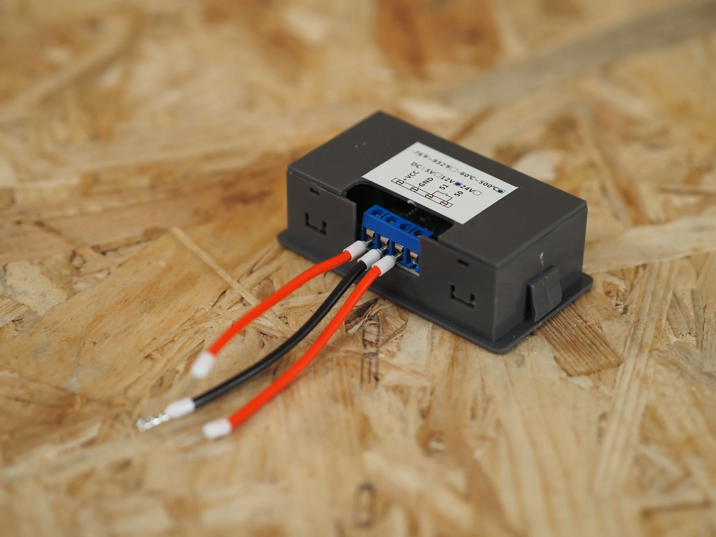
9cm Bootlace - Bootlace Red Cable (x2)
Insert the two 9cm Bootlace - Bootlace Red Cables into the two terminals labelled VCC and S1 then tighten down the screws.

Step 35
Locate this cutout on the Main Body.

Step 36
From the inside of the Main Body, pull one of the cables from the 40W Cartridge Heater out of the cutout.

Step 37
Insert this cable into the terminal labelled S0 (it doesn't matter which cable from the Cartridge heater) and tighten down the screw.

Step 38
From the inside of the Main Body, pull the cables from the K-Type M3 Thermocouple out of the cutout.
Step 39
Remove the PID’s back housing and locate the two green fork terminals.
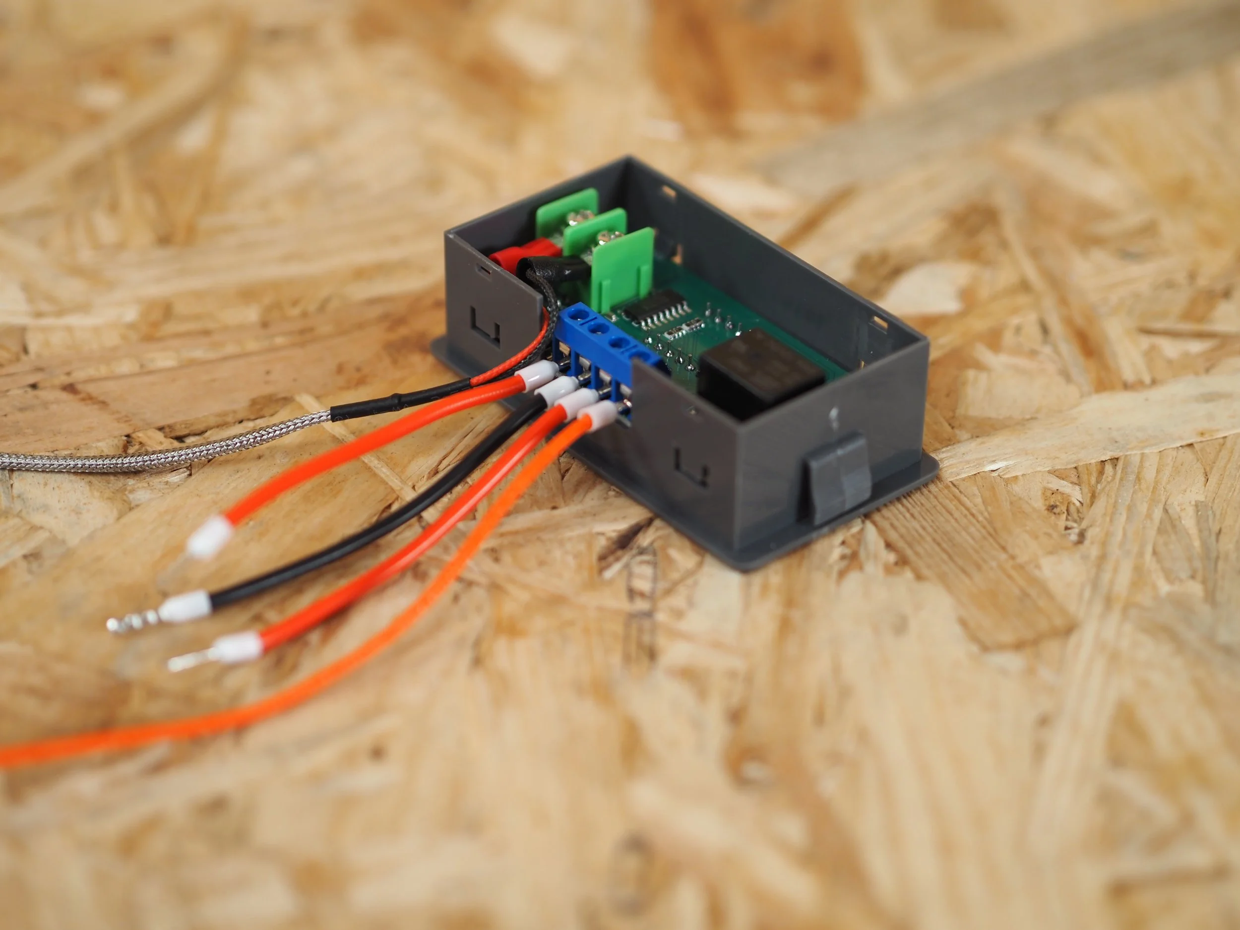
Step 40
Plug the M3 K-Type Thermocouple cables into the two fork terminals. Ensure the positive fork (Red) is plugged into the left terminal and the negative fork (Black) is plugged into the right terminal as shown.
Step 41
From the outside of the Main Body, feed the cables from the PID Controller into the cutout and reattach the PID Controller’s back housing.

Step 42
Insert the PID Controller down into the cutout at a 45° angle, making sure the wires are positioned to sit inside the Main body.

Step 43
Rotate and Align the PID Controller so that it sits perpendicular to the cutout on the main body.

Step 44
Press down the PID Controller into the cutout so that it sits flush with the main body.

Step 45
On the Main Body locate the two holes that sit either side of the logo.

Step 46
You will need:
M3x6mm Button Bolt (x2)
Either side of the logo insert two M3x6mm Button Bolts.

Step 47
You will need:
Logo Plate (x1)
On the inside of the Main Body, place the Logo Plate up against the two M3x6mm Button Bolts and tighten. The bolts will create a thread in the plastic so you may need to use a bit of force to get this started, being careful not to over tighten the bolts.

Step 48
Rotate the Main Body on to its side to match the image.

Step 49
On the inside of the Main Body locate the three holes for the Fan Mount.

Step 50
You will need:
Fan Mount (x1)
Take the Fan Mount and identify the side with the chamfered edge and three holes.

Step 51
Place the Fan Mount against the three corresponding holes, making sure the side with the chamfered edge and three holes is sat against the back of the Main Body.

Step 52
From the outside of the Main Body locate the bottom left Fan Mount hole.

Step 53
You will need:
M4x8mm Button Bolt (x1)
Place the M4x8mm Button Bolt into the bottom left Fan Mount hole and tighten. The bolt will create a thread in the plastic so you may need to use a bit of force to get this started, being careful not to over tighten the bolts.

Step 54
You will need:
12V 5015 Fan (x1)
From the inside of the Main Body place the 12v 5015 Fan up against the Fan Mount. Ensure that the fan blades are facing the Fan Mount and the fan output is facing upwards towards the rectangular cutout.

Step 55
You will need:
M4x40mm Button Bolt (x2)
From the outside of the Main Body, insert the two M4x40mm Button Bolts through the Fan Mount and 12v 5015 Fan.

Step 56
You will need:
M4 Lock Nut (x2)
From the inside of the Main Body, place the two M4 Lock Nuts over the M4x40mm Button Bolts and tighten.
Step 57
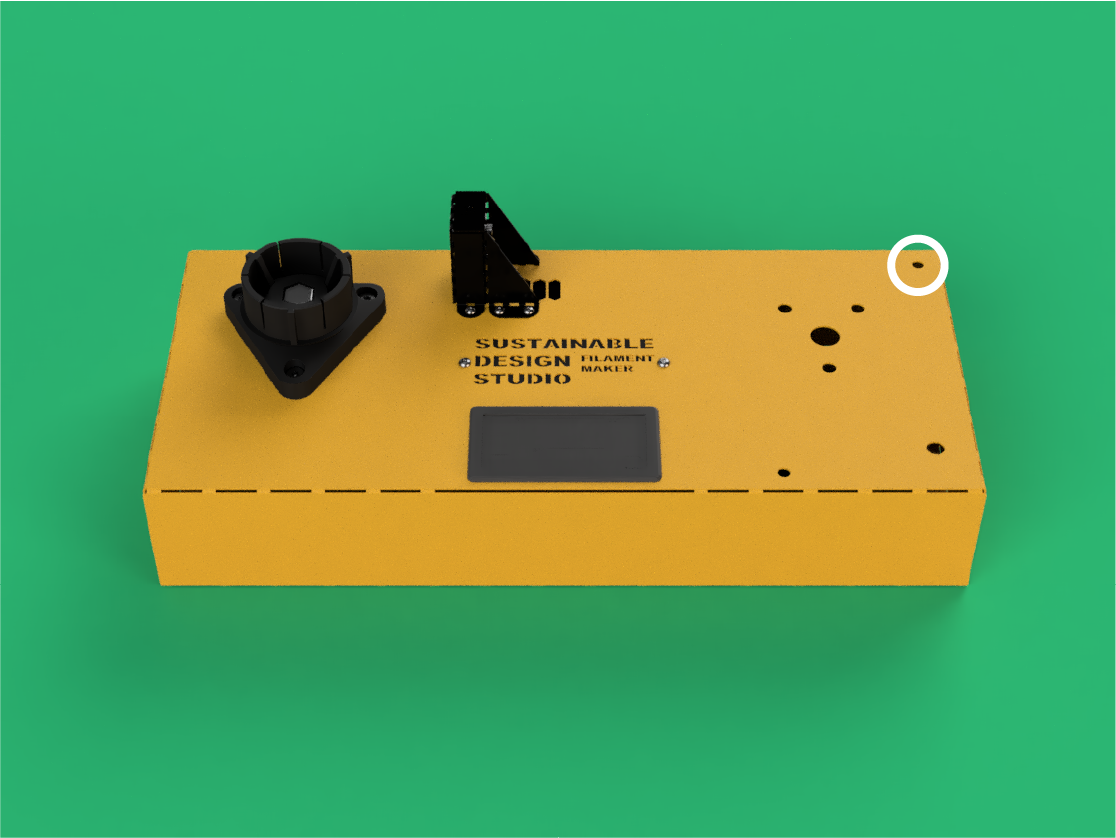
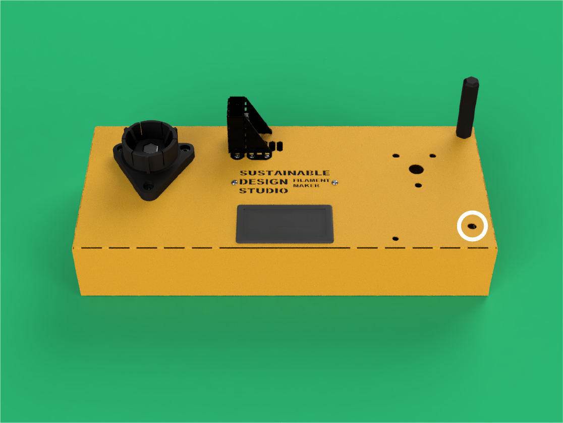
Locate the hole on the top right of the Main Body as shown in the image.

Step 58
You will need:
M5x55mm Cylindrical Bolt (x1)
From the inside of the Main Body insert the M5x55mm Cylindrical Bolt.

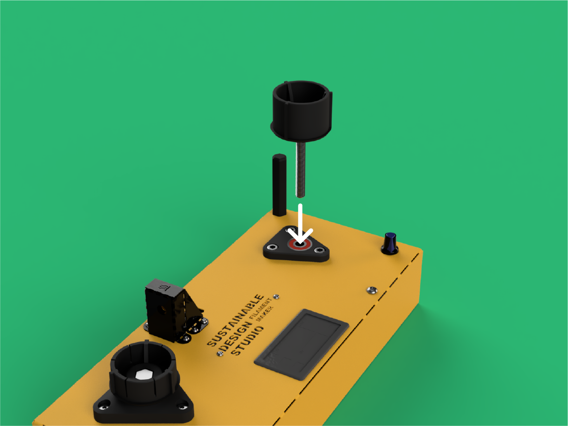
Step 59
You will need:
Pulley Spool Protector (x1)
Use a 13mm spanner to screw the M5x55mm Cylindrical Bolt into the Pulley Spool Protector. The bolt will feel loose in this part, however the top of the Pulley Spool Protector has a thread in it, you may need to use some force to get the bolt to catch.

Step 60
You will need:
Pulley Spool Motor Housing (x1)
608ZZ Bearing (x1)
Take the Pulley Spool Motor Housing and press one of the remaining 608ZZ Bearings into it as shown in the image.

Step 61
You will need:
M6 Lock Nut (x3)
Place the three M6 Lock Nuts thread down into Pulley Spool Motor Housing.

Step 62
You will need:
M5 Lock Nut (x1)
Place the M5 Lock Nuts thread down into Pulley Spool Motor Housing.

Step 63
You will need:
12V 10RPM JG370 Motor (x1)
Pulley Spool 10T Gear (x1)
Take your 12V 10RPM JGY370 Motor and place the Pulley Spool 10T Gear onto its shaft. Make sure to line up the flat side of the motor’s shaft with the flat cutout of the gear.

Step 64
You will need:
24cm 2.2mm Spade - Bootlace Red Cable (x1)
24cm 2.2mm Spade to Bootlace Black Cable (x1)
Motor Cover Connector (x1)
Feed the 24cm 2.2mm Spade - Bootlace Red Cable and the 24cm 2.2mm Spade - Bootlace Black Cable through the Motor Connector Cover as shown. Make sure the cables are placed in the correct way. The red cable placed through the hole marked with + and the black cable through the hole marked with -

Step 65
Plug in the 12V 10RPM JGY370 Motor as shown. Ensuring that the polarity matches the picture, and that you have fed the correct cable through the correct hole of the Motor Connector Cover.

Step 66
Slide the Motor Connector Cover over the connections and 12V 10RPM JGY370 Motor.

Step 67
You will need:
PWM Controller (x1)
Take the PWM Controller and loosen the four terminal screws. Put the Knob, Washer and Nut aside for use later.

Step 68
You will need:
24cm Bootlace - Bootlace Red Cable (x1)
Insert the 24cm Bootlace - Bootlace Red Cable into the port on the PWM labelled V+.

Step 69
You will need:
24cm Bootlace - Bootlace Black Cable (x1)
Insert the 24cm Bootlace - Bootlace Black Cable into the port on the PWM labelled V-.

Step 70
Locate the mount for the PWM Controller on the Pulley Spool Motor Housing.

Step 71
Take the PWM Controller and place it on the Pulley Spool Motor Housing.

Step 72
You will need:
M2.5x6mm Cylindrical Bolt (x2)
Screw the PWM Contoller into the Pulley Spool Motor Hosuing using the two M2.5x6mm Cylindrical bolts.

Step 73
Feed the 24cm Bootlace - Bootlace Red Cable and the 24cm Bootlace - Bootlace Black Cable from the PWM Controller through the Pulley Spool Motor Housing.

Step 74
You will need:
12V 10RPM JGY370 Motor (x1)
Place the 12V 10RPM JGY370 Motor into the Pulley Spool Motor Housing.

Step 75
Feed the 24cm 2.2mm Spade - Bootlace Red Cable and the 24cm 2.2mm Spade - Bootlace Black Cable from the 12V 10RPM JGY370 Motor through the Pulley Spool Motor Housing.

Step 76
Insert the 24cm 2.2mm Spade - Bootlace Red Cable into the port on the PWM labelled M+.

Step 77
Insert the 24cm 2.2mm Spade - Bootlace Black Cable into the port on the PWM labelled M-.

Step 78
You will need:
Pulley Spool Motor Spacer (x1)
Place the Pulley Spool Motor Spacer on top of the 12V 10RPM JGY370 Motor.
Step 79
On the top of the Main Body locate the hole as shown.

Step 80
Place the Pulley Spool Motor Housing into the Main Body making sure that the PWM Controller sticks through the previously located hole.
Step 81
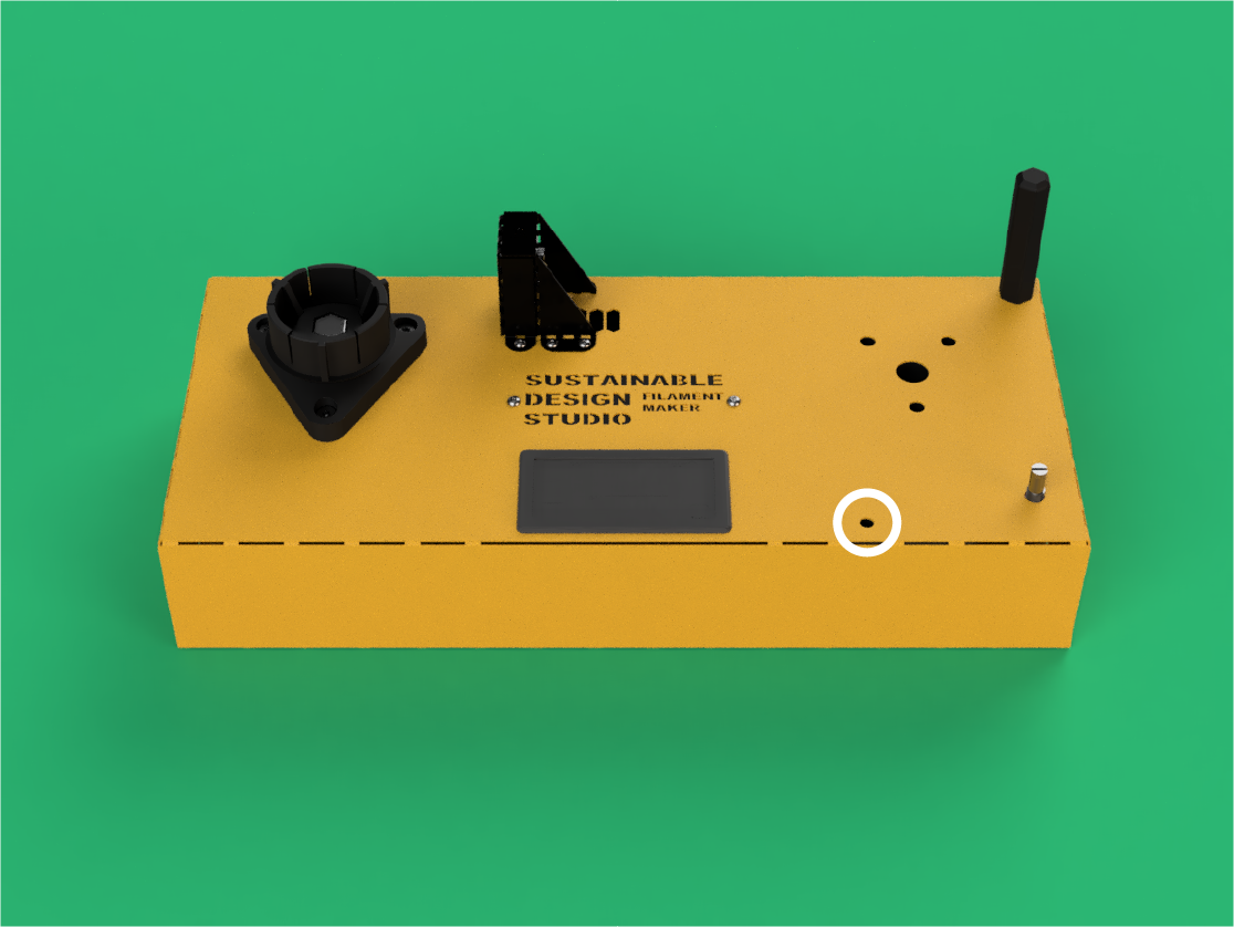
On the top of the Main Body locate the hole as shown.

Step 82
You will need:
M5x35mm Button Bolt (x1)
Place in the M5x35mm Button Bolt and tighten down.

Step 83
You will need:
Pulley Spool Mount (x1)
6008ZZ Bearing (x1)
Take the Pulley Spool Bearing Mount and press the last of the bearings into it until the 6008ZZ Bearing sits flush.

Step 84
Locate these four holes on the Main Body.

Step 85
Place and allign the Pulley Spool Bearing Mount over the holes.

Step 86
You will need:
M6x30mm Cylindrical Bolt (x3)
Place the three M6x30mm Cylindrical Bolts into the Pulley Spool Bearing Mount and tighten.

Step 87
On the top of the Main Body place the PWM Washer onto the PWM Controller.

Step 88
Place the PWM Nut onto the PWM Controller and tighten

Step 89
Rotate the PWM counterclockwise until it clicks and can’t be rotated any further.

Step 90
Place the Black PWM Knob onto the PWM as shown. Push down until it wont go any further.

Step 91
You will need:
M8x70mm Hex Bolt (x1)
Pulley Spool Mount (x1)
Place the M8x70mm Hex Bolt into the Pulley Spool Mount ensuring that the hexagonal head is pushed fully into the hexagonal cutout of the Pulley Spool Mount.

Step 92
You will need:
M8 Washer (x1)
Slide an M8 Washer onto the M8x70mm Hex Bolt.
Step 93
Insert the M8x70mm Hex Bolt through the 6008ZZ Bearings of Pulley Spool Bearing Mount and Pulley Spool Motor Housing.

Step 94
You will need:
M8 Washer (x1)
On the inside of the Main Body, slide an M8 Washer over the M8x70mm Hex Bolt.

Step 95
You will need:
M8 Hex Nut (x1)
Pulley Spool 34T Gear (x1)
Insert the M8 Hex Nut into the hexagonal cutout on the Pulley Spool 34T Gear.

Step 96
Pull out the M8x70mm Hex Bolt slightly to make room for the Pulley Spool 34T Gear.

Step 97
Place the Pulley Spool 34T Gear over the M8x70mm Hex Bolt.

Step 98
By turning the Pulley Spool Mount, tighten the M8x70mm Hex Bolt into the Pulley Spool 34T Gear. This should be tightened down enough so that there is no wobble in the Pulley Spool Mount. Do not over-tighten.

Step 99
You will need:
M8 Lock Nut (x1)
Place the M8 Lock Nut onto the M8x70mm Hex Bolt and tighten it down against the M8 Hex Nut that's in the Pulley Spool 34T Gear.

Step 100
Locate these cutouts on the back of the Main Body

Step 101
You will need:
24cm 2.2mm Spade - Bootlace Black Cable (x1)
9cm 4.8mm Spade - 2.2mm Spade Red Cable (x1)
Power Supply Cover (x1)
Insert the 24cm 2.2mm Spade - Bootlace Black Cable and the 9cm 4.8mm Spade - 2.2mm Spade Red Cable through the Power Supply Cover.

Step 102
You will need:
5A Panel Mount DC Socket (x1)
Remove the silver Nut from the 5A Panel Mount DC Socket and place the Nut over the cables from the previous step.

Step 103
From the inside, place these cables through the circular cutout on the Main Body.

Step 104
Plug the cables onto the 5A Panel Mount DC Socket, making sure the black cable is plugged onto the longer pin of the socket.
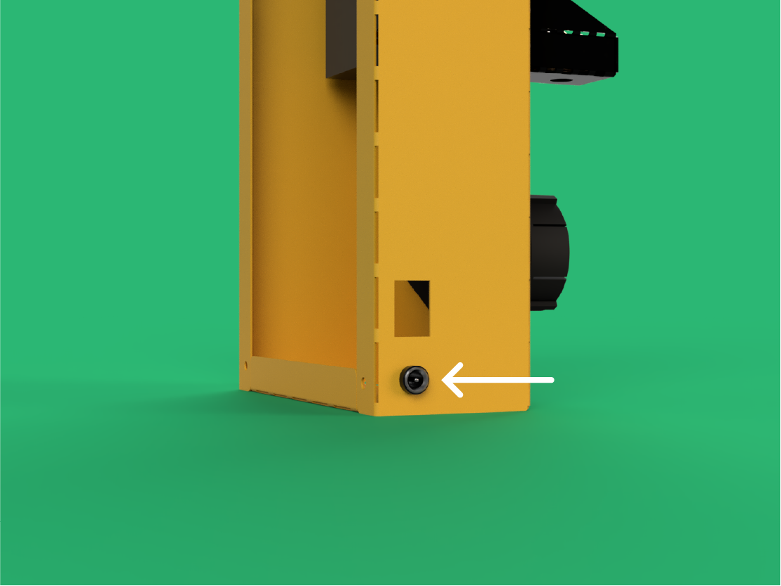
Step 105
Push the 5A Panel Mount DC Socket into the Main Body.

Step 106
Use the nut to tighten the 5A Panel Mount DC Socket to the Main Body.

Step 107
Slide the Power Supply Cover over the connections and 5A Panel Mount DC Socket.

Step 108
Place the other end of the 9cm 4.8mm Spade - 2.2mm spade red cable through the rectangular cutout of the Main Body

Step 109
From the inside, place 4.8mm Spade from the 24cm 4.8mm Spade - Bootlace Red Cable through the rectangular cutout as seen in the image.

Step 110
You will need:
12V ON/OFF Rocker Switch (x1)
Plug the cables onto the 12V ON/OFF Rocker Switch as shown.

Step 111
Push the 12V ON/OFF Rocker Switch into the Main Body so that it sits flush.

Step 112
You will need:
Wago 5 Way Connector (x1)
Take one Wago 5 Way Connector and open up all the ports.

Step 113
Plug in all the available Red Cables and close the Wago 5 Way Connector ports.
- One cable coming from the 12v ON/OFF Rocker Switch
- Two cables coming from the K-type PID Controller (VCC + S1)
- One coming from the 12v 5015 Fan
- One coming from the 12v PWM Motor Controller
DO NOT connect the Red Cable coming from the 40W Cartridge Heater.
Step 114
WhYou will need:
Wago 5 Way Connector (x1)
Take one Wago 5 Way Connector and open up all the ports.

Step 115
Plug in all the available Black Cables and remaining Red Cable of the 40W Cartridge Heater. Again close the Wago 5 Way Connector ports.
- One cable coming from the 5A Panel Mount DC Socket
- One cable coming from the K-type PID Controller (GND)
- One cable coming from the 12v 5015 Fan
- One cable coming from the 12v PWM Motor Controller
- One cable coming from the 40W Cartridge Heater

Step 116
You will need:
100mm Cable Tie (x3)
Neaten up the cables using the 100mm Cable Ties. These can be tightened down at two loop points on the Logo Plate.

Step 117
You will need:
M5x10mm Cylindrical Bolt (x4)
Feet (x4)
Screw the four M5x10mm Cylindrical Bolts into the four Feet.

Step 118
You will need:
Main Body Base (x1)
Place and align the Main Body Base against the bottom of the Main Body.

Step 119
You will need:
M5x6mm Button Bolt (x2)
Use the two M5x6mm Button Bolts to secure the Base in place to the two threaded points at the centre of your assembly.

Step 120
Screw the four M5x10mm Cylindrical Bolts and Feet into the remaining threaded holes and tighten.

Almost there!
You are now ready for the last few steps.
To assemble the last parts of your build, click the button below to be taken to the spool assembly page.