
Moulds: designing a 3D printed insert
Design a 3D printed insert mould in Fusion 360.
Eleven steps, two printing routes, and a finished example file to work from.
A 3D printed insert is a mould cavity you print yourself and drop into an aluminium housing. It gets you injection moulding a new part without commissioning an aluminium mould first. That matters when you are still testing a design, or when you only need a short run. Print it, inject, change something, print again the same day. An insert will not last like machined aluminium, so treat it as a tool for a run of parts rather than a production mould.
This guide uses Fusion 360 because it is free for personal use and it has the four commands the job needs: Split Body, Shell, Extrude and Combine. If you already work in another parametric CAD package, the same steps translate.
It does assume you can find your way around Fusion 360. If you have not used it before, run through Autodesk's introductory tutorials first, then come back.
What you need
The shared kit is the same whichever way you print. From there, pick one of two routes: an FDM printer running a high-temperature filament, or an SLA printer running a high-temperature resin.
Shared essentials
- Sustainable Design Studio Injection Mini machine
- A 3D printed resin holder mould (the aluminium housing)
- A computer running Autodesk Fusion 360
FDM route
- An FDM printer with high-temperature capability and a heated chamber, such as the Bambu Lab X1C
- Polycarbonate filament (higher melt temperature), such as Prusament PC Blend
SLA route
- An SLA printer, such as the Elegoo Saturn 3
- A high-temperature resin, such as Phrozen TR300 or Siraya Tech Sculpt Ultra White (+250°C, not as good as Phrozen TR300)
- A washing and curing station, such as the Elegoo Mercury X
Optional extras
- Fine-grit sandpaper (800-1200 grit)
- Silicone mould release spray (260°C)
Sustainable Design Studio can design your mould for 3D printing or aluminium.
Learn moreFAQ
Questions about 3D printed inserts
Still unsure? The team replies within one to two working days. Get in touch
Starter files
Download an insert block
Pick a block size, import it into Fusion 360, and use it as the starting solid for your mould. Or open the worked example and see a finished one.
The smallest starter block. Best for compact parts with a small footprint.
DownloadThe middle size. A good default for most everyday parts.
DownloadA wider footprint than the medium block, at the same depth. Good for broader, flatter parts.
DownloadThe largest starter block. Use it for long parts that will not fit inside the square blocks.
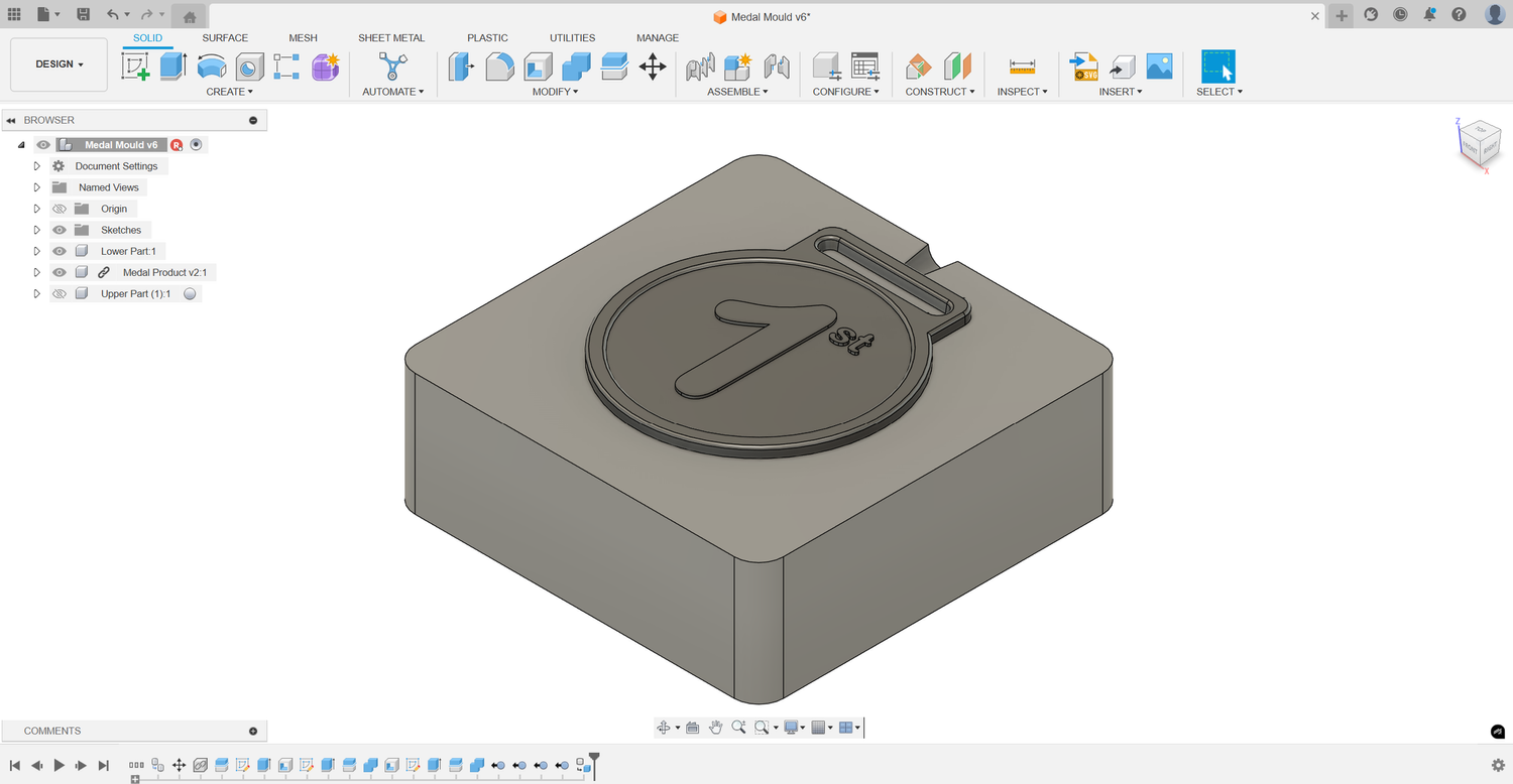
DownloadA finished medal mould you can open in Fusion 360 and pick apart. Useful if you would rather see a finished one before working through the steps.
DownloadStep by step in Fusion 360
Eleven steps from starter block to a finished mould ready for printing. Steps 6 to 10 apply only to SLA moulds. If you are making an FDM insert, follow steps 1 to 5 then skip straight to Step 11.
-
 Step 1
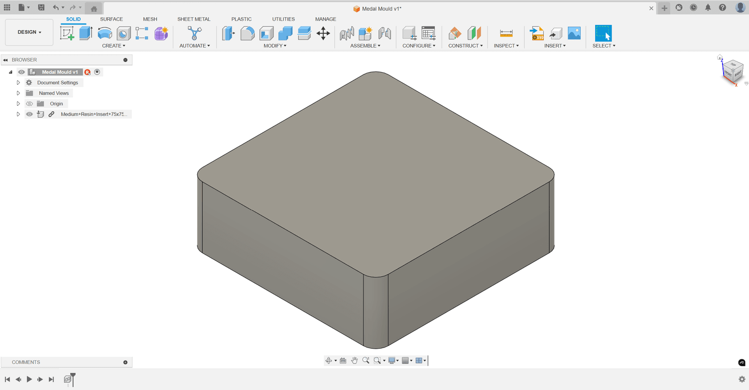
Download and import the block
Choose and download the block size you want from the files above (small, medium, or large). Open Fusion 360 and import the block into your workspace.
-
 Step 2
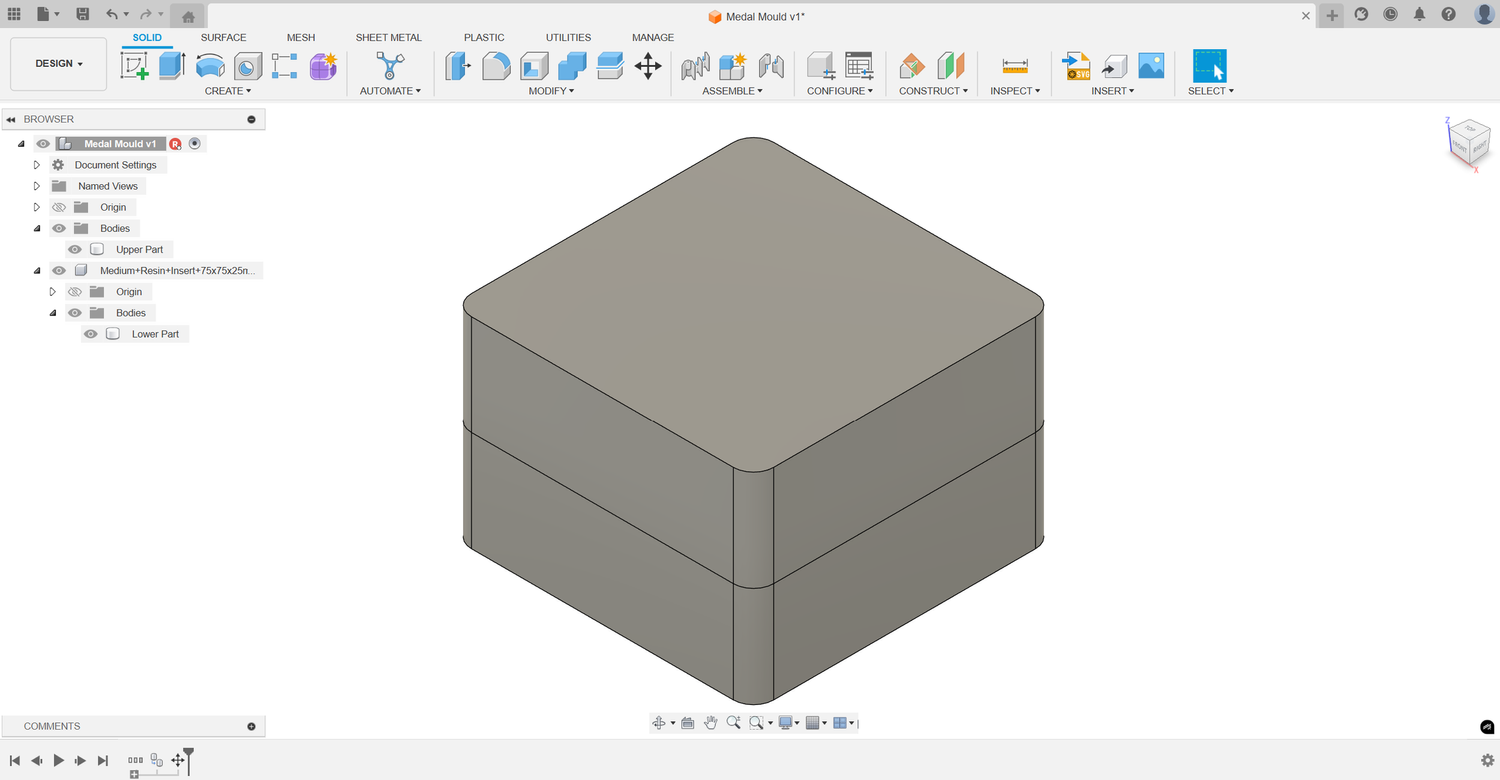
Create two copies of the block
Duplicate the block and stack one on top of the other, keeping them aligned.
-
 Step 3
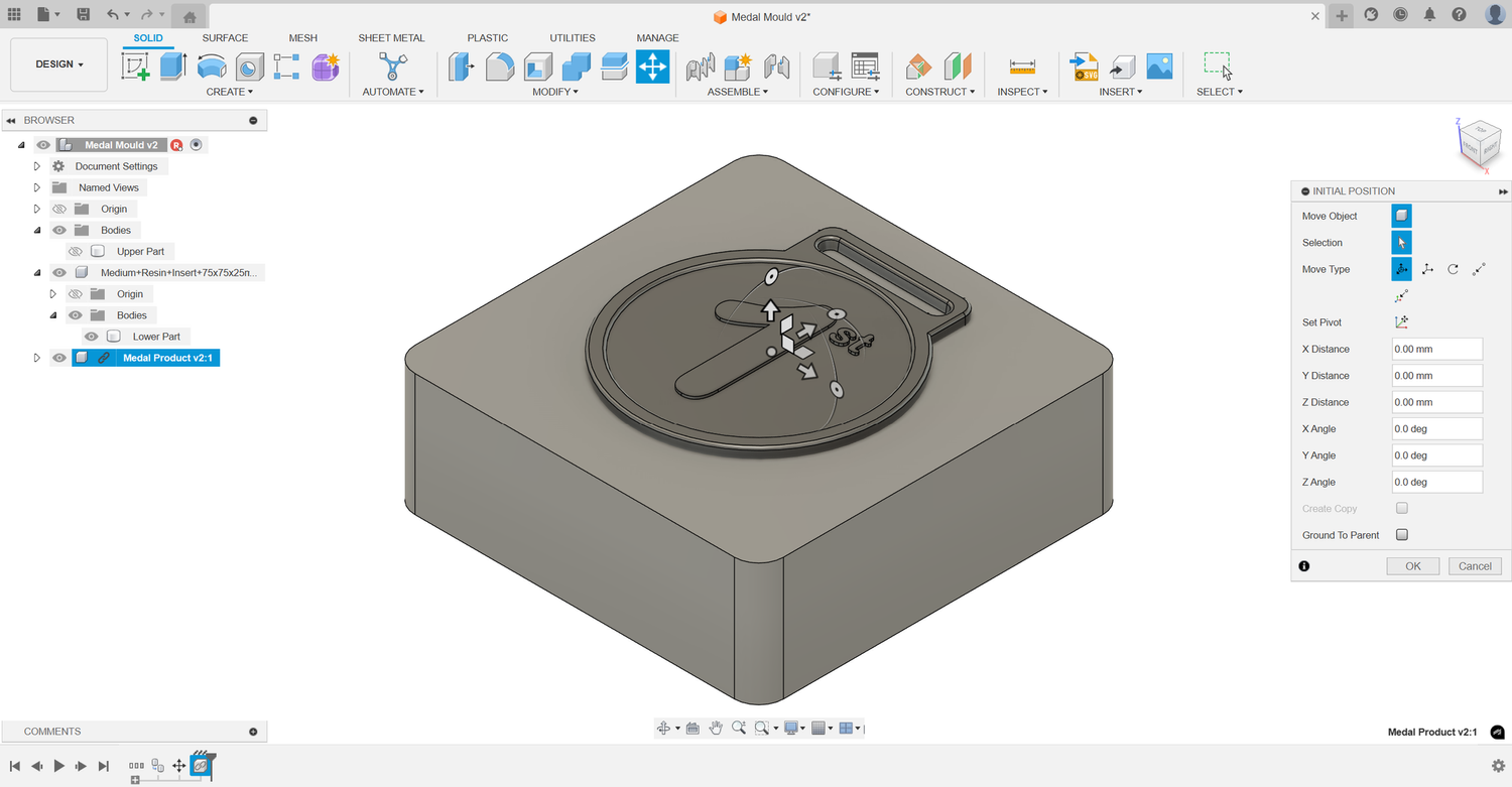
Import your object
Import the 3D model of the object you want to inject. Position it 50/50 between the two blocks and centred on the X and Y axis.
-
 Step 4
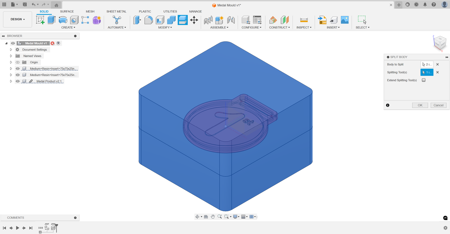
Split the blocks
Use the Split Body command. Select the two blocks as the bodies to split and the object as the splitting tool. Confirm to create the initial mould cavity.
-
 Step 5
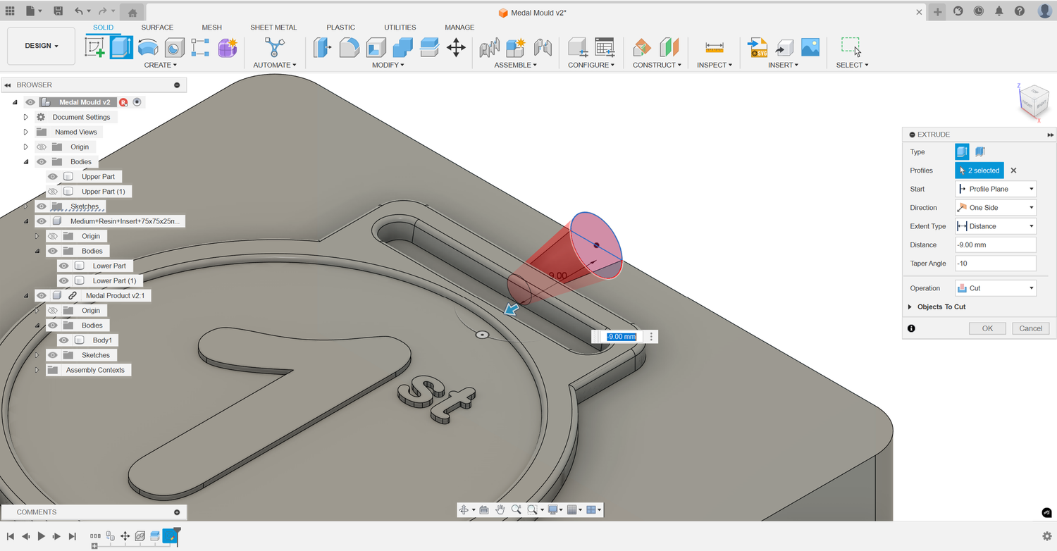
Add the injection point
On one of the four external side faces of the mould, sketch a 6mm circle aligned with the injection point on the aluminium housing. Use Extrude to cut into the mould until it intersects the product cavity, keeping the intersection diameter at 2-3mm.
-
Steps 6 to 10 are for SLA moulds only
If you are making an FDM insert, skip straight to Step 11.
-
 Step 6
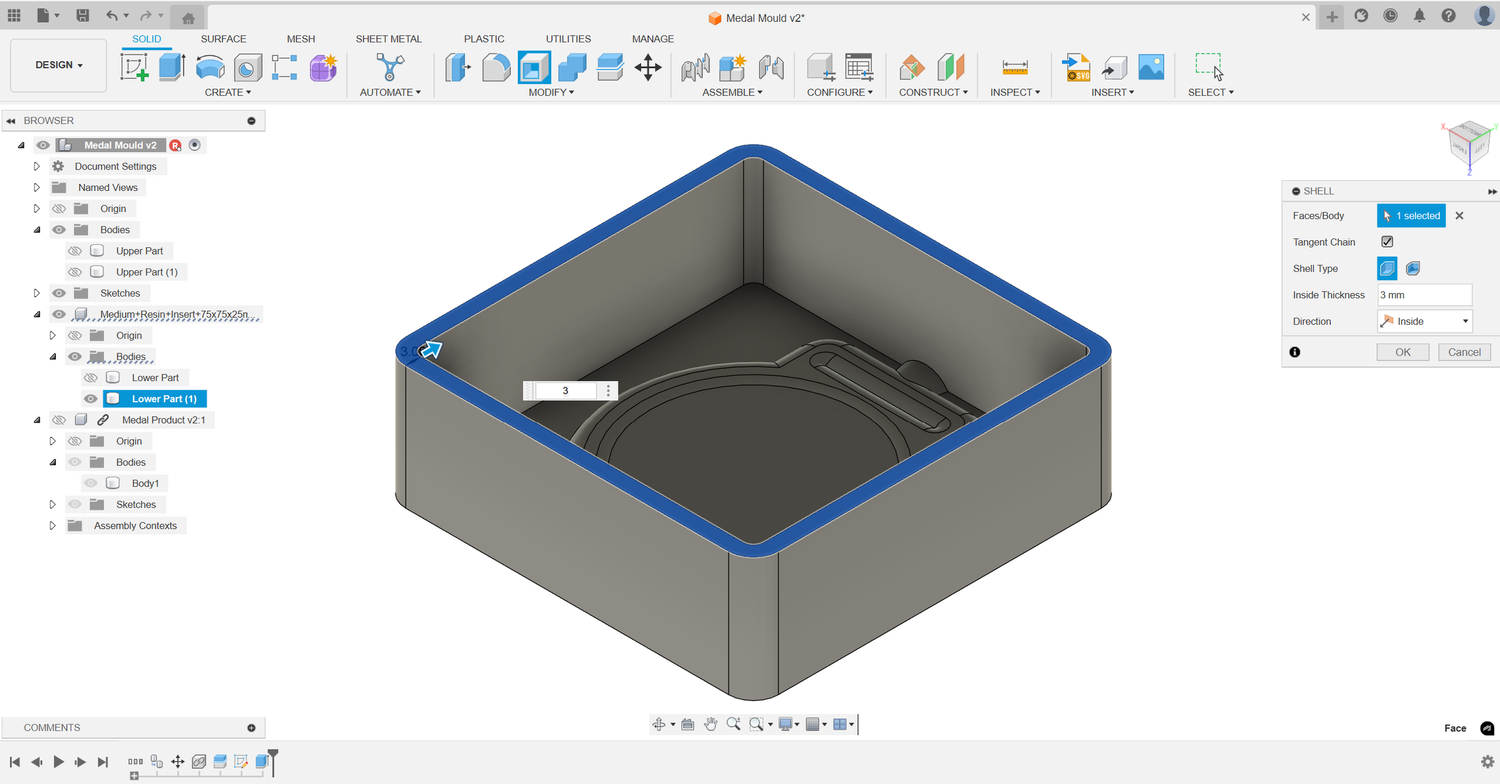
Hollow out the moulds (SLA only)
Use the Shell command to hollow out each mould half to a uniform 3mm thickness.
-
 Step 7
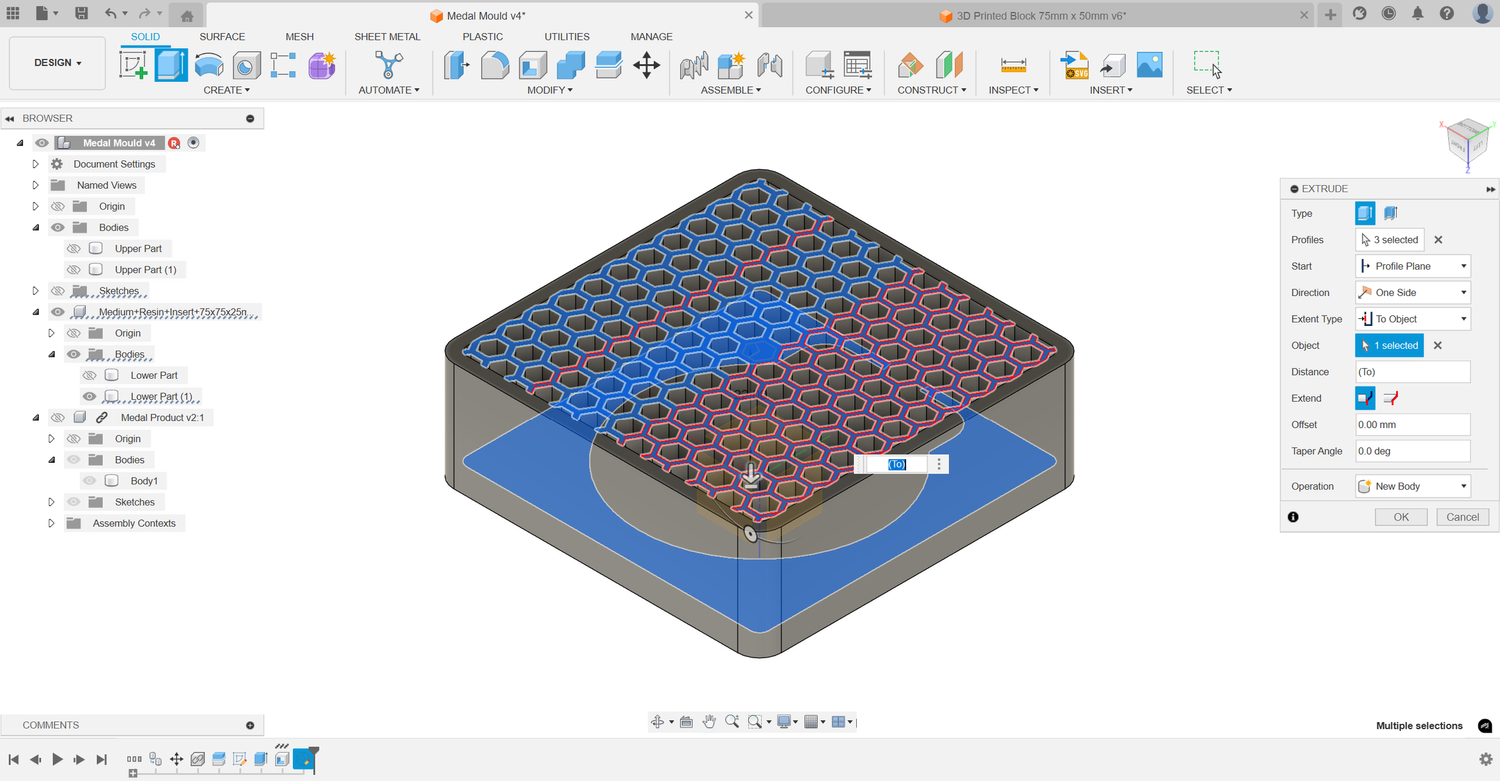
Add a hexagonal texture (SLA only)
On the mould face, sketch a hexagonal pattern and extrude it to create a textured surface.
-
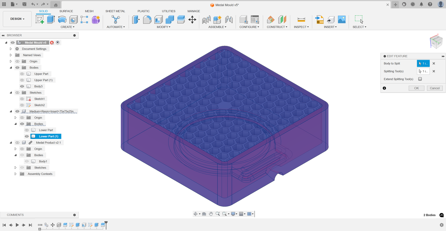 Step 8
Split the texture (SLA only)
Use the Split Body command to split the hexagonal texture with the hollowed-out mould halves.
-
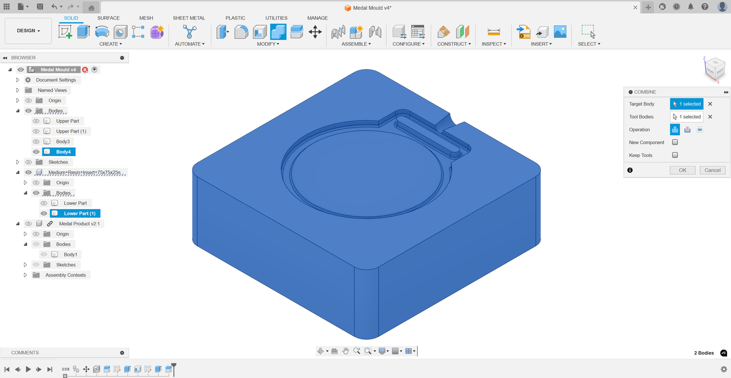 Step 9
Combine the parts (SLA only)
Use the Combine tool to merge the hexagonal pattern with the corresponding mould half.
-
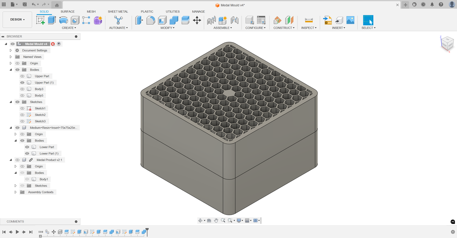 Step 10
Repeat for the other half (SLA only)
Follow steps 6 to 9 to finish the second half of the mould.
-
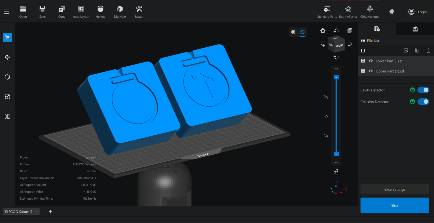 Step 11
Finalise and export
Your mould is complete and ready for printing and assembly. Export it as an .STL file to the slicer of your choice.
Tips
Two habits that get more shots out of an insert before it fails.
Always inject at the lowest temperature that works
Start low and only raise the barrel temperature if the part will not fill. Excess heat is hard on a 3D printed insert and shortens how many times you can use it before it breaks down.
Always inject at the lowest injection pressure that works
Use just enough pressure to fill the cavity cleanly. Lower pressure reduces the force on the delicate insert and helps prevent flashing, overflow, and breakages.
Related resources
Five picks from the Sustainable Design Studio resources library to read alongside this guide.
3D printing vs injection moulding
A full breakdown of the pros and cons of injection moulding compared to 3D printing.
Mould use
Everything you need to know about using our moulds and handling common problems.
How to inject PLA
Turn 3D printing waste into eco-friendly products with the Injection Mini.
How to 3D print SLA moulds
A guide to 3D printing an SLA mould, what to buy, and the full DIY process.
Good product design
A comprehensive guide to what makes a good, and a bad, recycled product.
Made something with your mould?
Share your creations with us on social media, we love seeing what you all make. Got a question? Send us a message.